

Important Safety Precautions
This section describes the safety requirements that must be met during the installation and operation of the OmniPicker 3. As OmniPicker 3 is a partly-completed machinery, it is essential to carefully read this manual and fully understand the relevant safety features and potential hazards prior to first use. All relevant personnel must conduct risk assessment before each OmniPicker 3 installation and strictly adhere to all instructions in this manual during operation.
1.1 Notes for Use
Do not place OmniPicker 3 in environments with high temperature, high humidity, or flammable or explosive substances. Keep it away from open flames, and do not operate it in strong electromagnetic fields, such as near high-voltage power lines or high-power machinery.
Do not apply excessive force to the gripper fingers or pull the gripper forcibly. Do not subject OmniPicker 3 to excessive loads or impacts.
Do not use OmniPicker 3 to grasp objects that are excessively heavy, hot, sharp, rough-surfaced, or corrosive.
Do not use OmniPicker 3 to operate hazardous machinery. The Company accepts no liability for personal injury or property damage resulting from such use.
Do not touch the surfaces of OmniPicker 3 during or immediately after operation, as they may become hot and cause burns.
Do not allow minors to operate OmniPicker 3 unsupervised. Where use is necessary, it must take place under the continuous supervision and guidance of a qualified adult.
Do not perform powered operation or commissioning without having received product safety training and familiarity with the operating logic and safety rules of the equipment.
Do not operate OmniPicker 3 under the influence of alcohol or fatigue, or after taking medication that impairs judgment or reaction time. Do not allow persons with impaired mobility or cognitive ability to operate OmniPicker 3 unsupervised.
Before operation, make sure all cables, plugs, and sockets are intact. Disconnect the power supply immediately if an abnormal condition occurs, such as a short circuit or overheating.
1.2 Risk Assessment
List of Potential Hazards:
Mechanical hazards: Crush injuries, abrasions, etc., caused by contact with the OmniPicker 3 or any sharp object being held.
Electrical hazards: Electric burns or electric shock from contact with live parts.
High-temperature hazards: Skin burns from prolonged contact with hot surfaces of OmniPicker 3.
Noise hazard: No significant hazard identified.
Vibration hazard: No significant hazard identified.
Radiation hazard: No significant hazard identified.
Material/substance hazard: No significant hazard identified.
Ergonomic hazard: Pinching injuries from contact with gaps between components.
Environmental hazards: No significant hazard identified.
1.3 Warranty and After-Sales Service
OmniPicker 3 is covered by a 6-month limited warranty. If any defect due to manufacturing or material flaws occurs after the Product is put into use, we(the Company) will provide necessary spare parts for replacement or repair. The product warranty shall be void if defects result from improper handling, failure to follow the instructions provided in the manual, or unauthorized disassembly of the product. Without prejudice to the terms of this warranty, if the Product has exceeded its warranty period, we reserve the right to charge customers for the cost of replacement or repair.
Beyond the warranty period, if the device exhibits any defect, we shall not be held liable for any damages or losses incurred, including but not limited to production losses or damage to other production equipment.
Except for the operations expressly permitted in this manual, unauthorized disassembly of the Product is strictly prohibited. Otherwise, the warranty-related clauses in the Hardware Sales Agreement will become invalid. If any malfunction occurs, please contact after-sales service personnel promptly.
Customers may separately purchase extended warranty services or OmniCare+ services. Please contact the sales or customer service team for details.
1.4 Disclaimer
We(the Company) are committed to continuously improving the product reliability and performance, and therefore reserve the right to make product improvements or upgrade without further notice. We strive to ensure the accuracy and completeness of this Manual but shall not be held liable for any errors or omissions it may contain. Due to ongoing product improvements, version updates, or typesetting and printing, the content of this Manual may differ from the actual product. The actual product and the latest information released by the Company shall prevail. If you find any error or omission, please contact us promptly. Defects or malfunctions caused by the following circumstances are not covered within the scope of warranty:
Failure to install, wire or connect other control devices as required by the user manual;
Unauthorized disassembly/assembly of OmniPicker 3;
Use of OmniPicker 3 beyond the specifications or standards stated in the user manual;
Damage resulting from improper transportation;
Damage caused by accidents, impacts, or collisions;
Damage caused by natural disasters, including but not limited to fire, earthquakes, tsunami, lightning strikes, strong winds and floods;
Hot-plugging of power or signal cables while the gripper is powered on is not supported. Users must follow the specified operating procedures; the customer shall bear the corresponding responsibility for any fault caused by hot-plugging that does not comply with these requirements;
Any product damage or other loss caused by the use of non-specified tools, or by disassembly or assembly not performed according to the specified method, shall be borne by the operator.
We shall not be held liable for any loss, damage, injury or expense caused by customers violating the disclaimers in this Section. Customers are kindly requested to carefully read and agree to this disclaimer before purchasing and using the Product.
1.5 Maintenance and Storage Instructions
To ensure the long-term stable operation of OmniPicker 3, please follow the maintenance and storage requirements below.
For long-term storage, it is recommended to store the product in a dry environment with suitable temperature, away from direct sunlight, corrosive gases, strong electromagnetic interference, fire sources, and heat sources.
During long-term storage, disconnect the power cable and communication cable. Avoid keeping the gripper under continuous load, bending, compression, or suspended conditions for extended periods. It is recommended to use the original packaging or protective packaging with dust-proof and shock-resistant features for storage.
Without proper protection, OmniPicker 3 must not come into contact with liquids (such as alcohol, water, beverages), dust, or corrosive substances. Avoid exposure to rain. If accidental contact occurs, immediately disconnect the power supply and inspect the interfaces, joints, and housing condition.
Do not soak OmniPicker 3 in water or spray cleaning liquids onto it. Do not use alcohol, strong acids, strong alkalis, corrosive cleaners, volatile solvents, or abrasive materials to clean the gripper. A clean, dry soft cloth may be used to wipe the surface of the rigid housing to remove dust.
Regular maintenance and inspection should be performed to ensure that components such as motors and power systems operate normally, preventing potential hazards caused by aging or damage.
If the gripper malfunctions, do not disassemble it yourself or continue forced operation. Record the fault symptoms, occurrence time, operating environment, load conditions, and abnormal warnings, then contact after-sales service personnel promptly. Damage caused by unauthorized repair, disassembly, modification, or use of non-original spare parts may invalidate warranty coverage. Related risks shall be borne by the user.
Product Introduction
2.1 Product Overview
OmniPicker 3 is a high-performance, cost-effective industrial two-finger gripper. Lightweight and fast-acting, it combines tactile sensing, strong gripping performance, and data-collection-friendly design. It serves as a standard end effector for humanoid robots and is widely applicable to embodied industrial data collection and task execution.
2.2 Product Highlights
Steady · Lightweight and powerful Under 800g in total weight with 140N gripping force, delivering an exceptional force-to-weight ratio and stable handling of 5kg payloads.
Precise · Absolute pressure sensing High-precision absolute pressure sensing. Force values can be set directly, remain consistent across devices, and do not drift over time.
Fast · Rapid actuation Minimum closing time of 0.4s, significantly improving grasping cycle time and data collection efficiency.
Wide · Extended stroke Maximum stroke of 110±5mm with enveloping grasp support, covering a broader range of object sizes.
Million-cycle service life High-strength aluminum alloy and alloy steel construction, with a service life of over one million cycles.
Modular design Multiple finger options are available for different workpieces, and the tactile module can be replaced independently without returning the entire unit for service.
AI-Native data collection Deeply compatible with data collection systems, with optional finger-mounted tactile sensing and cameras. Collected data can be used directly for model training.
2.3 Product Specifications
Basic Parameters | |
Weight | <800g |
Dimensions | Body length 98.5mm (excluding linkage and fingers) Maximum width 165mm Thickness 60mm |
Opening/closing time | 0.4s @ 60mm |
Maximum gripping force | 140N |
Maximum stroke | 110±5mm |
Finger Repeatability | ±0.1mm |
Payload | Rated 3kg / Maximum 5kg |
Operating voltage | Nominal 24V, range 24~80V |
Operating current | Rated 0.125A (6mm, 100N), peak 5A/10ms |
Communication interface | CAN-FD, RS485 |
Operating temperature | -10~45°C, up to 85% RH(non-condensing) |
Firmware upgrade | OTA upgrade supported |
Tactile Sensor Parameters | |
Sensor Type | Piezoresistive strain-fusion sensor |
Force resolution | 0.1N |
Tactile Points | 70 (single finger) |
Sensing Range | 0–200 N (specified accuracy within 0–25 N) |
Notes:
[1] The parameters in the tables above may vary depending on the application scenario and model configuration. The actual product shall prevail.
[2] RS485 is intended for secondary development and integration with customer systems. The host software currently supports CAN-FD connection only.
[3] The product appearance may be subject to future updates. The actual product shall prevail.
2.4 Appearance and Dimensions
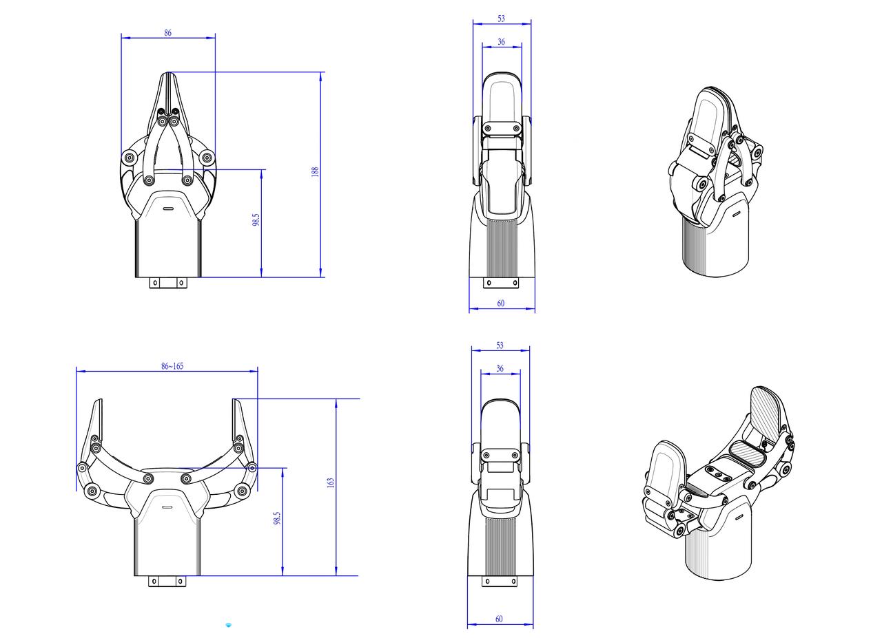
2.5 Tactile Point Distribution
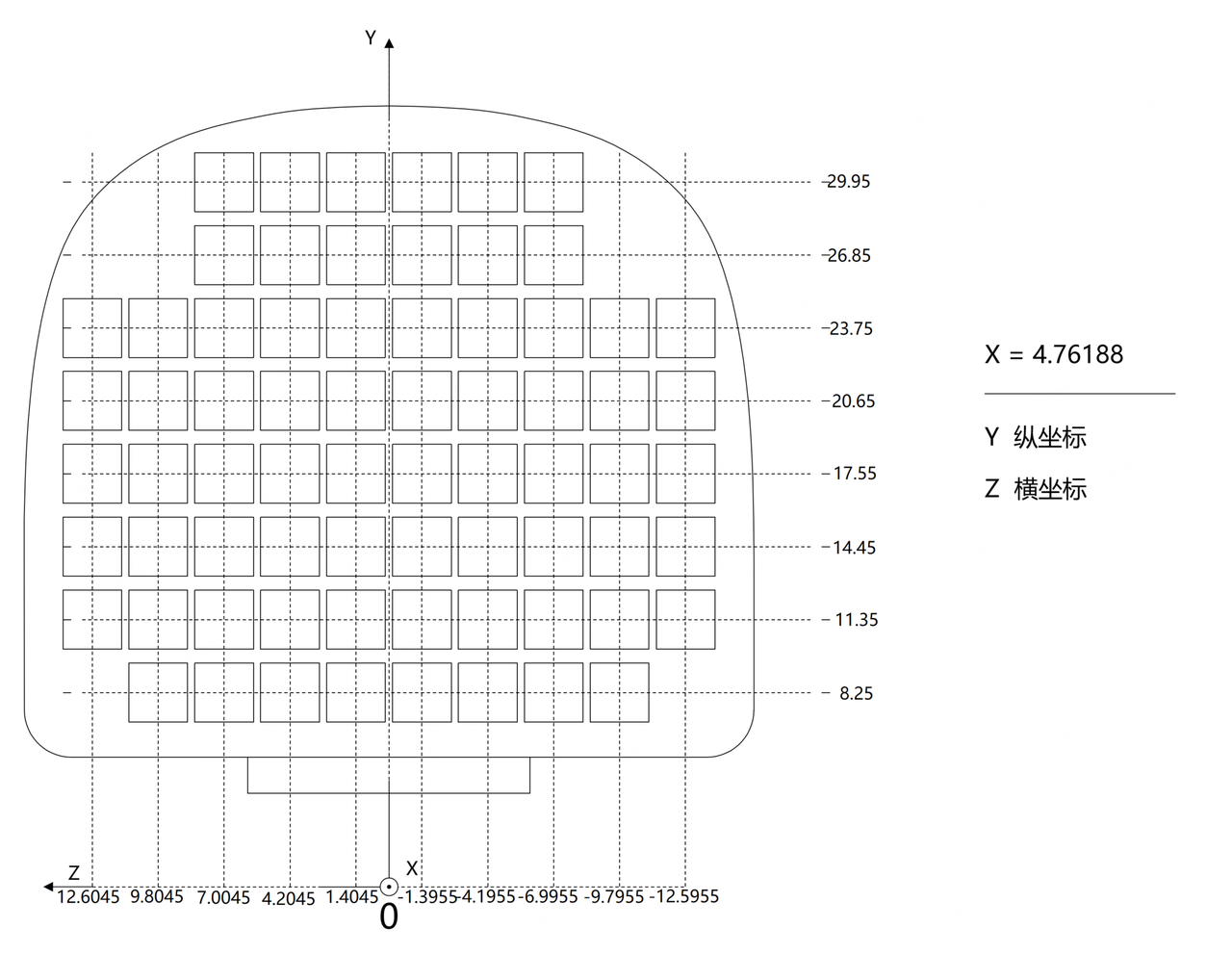
All coordinates in this section are given in millimeters.
The measurement reference frame is the end-effector finger frame of the standard OmniPicker 3 URDF model. The positive X direction points outward, perpendicular to the page.
The tactile array consists of 70 points in total. All points share a constant X coordinate of 4.76 mm — that is, they lie on the same plane at X = 4.76 mm — and are arranged in a regular rectangular grid of 8 rows × 10 columns in the Y–Z plane.
2.6 Environmental Protection and Disposal Declaration
This product is classified as Waste Electrical and Electronic Equipment (WEEE). When disposing of this product, please follow the requirements of the WEEE Directive.
The product must not be disposed of together with ordinary household waste. After the product reaches the end of its service life, it should be delivered to a qualified local electronic waste recycling facility for professional classification, recycling, and harmless disposal. Proper disposal helps recover valuable resources and reduces potential impacts on the ecological environment.
This product strictly complies with RoHS environmental protection regulations. The content of hazardous substances in all product components meets the legally defined limits.
2.7 Manufacturer Information
Manufacturer Name | AGILINK Innovations & Intelligence Technology Co., Ltd. |
|---|---|
Manufacturer Address | Room 1107, 11F, No. 185 Tianping Road, Xuhui District, Shanghai |
Contact | 021-20960883 |
Unboxing and Installation Guide
3.1 Packing List
OmniPicker 3 Packing List (Standard Items) | ||
|---|---|---|
No. | Description | Quantity |
1 | OmniPicker 3 (with dust bag) | 1 |
2 | Combined communication & power cable (incl. CANFD/RS485 communication) | 1 |
3 | Quick-start guide (one-pager) | 1 |
4 | Factory certificate of conformity | 1 |
5 | Captive screws (M4*8) | 7 |
6 | Hex wrench | 1 |
7 | Screw/wrench packaging bag | 1 |
The table above lists all standard items included with the product. Please check the contents of this list after unpacking.
The following optional accessories are not included in the standard packing list and can be purchased separately as needed: power adapter and power adapter cable, single-channel USB-to-CAN-FD adapter.
3.2 Installation Instructions
This section describes the materials, tools, and procedures required to install OmniPicker 3 on a robotic arm or an adapter flange.
3.2.1 Design the Adapter Flange
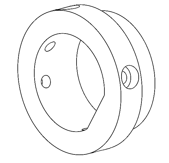
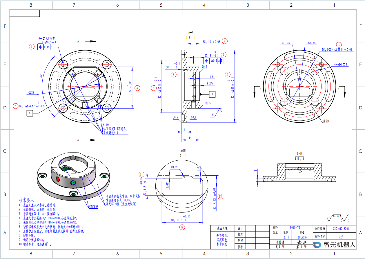
Based on the flange dimensions at the OmniPicker 3 mounting end (see Section 4.1 Mechanical Interface for flange specifications), design an adapter flange that connects OmniPicker 3 on one side and your robotic arm or other equipment on the other.
The following installation procedure uses the adapter flange designed in this document as an example.
 |
3.2.2 Required Materials and Tools
No. | Item | Quantity |
|---|---|---|
1 | OmniPicker 3 | 1 |
2 | M4*8 hex socket head cap screw (screw length varies with the adapter flange dimensions) | 5 |
3 | Adapter flange | 1 |
4 | 3mm hex key (3mm across flats) | 1 |
3.2.3 Installation Procedure
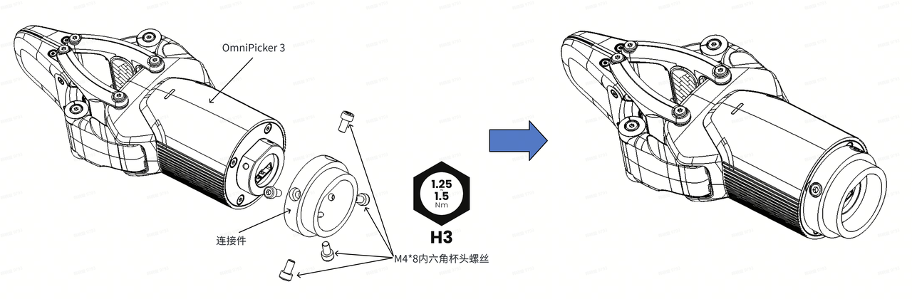
STEP 1: As shown in the figure, prepare one OmniPicker 3, one adapter flange (already matched to the OmniPicker 3 flange), and five M4×8 hex socket head cap screws. The screw length depends on the dimensions of the adapter flange; 8 mm is used in this example. Ensure that the thread engagement length inside the OmniPicker 3 flange is at least 4 mm.
STEP 2: As shown in the figure, mount OmniPicker 3 onto the adapter flange and tighten the five M4 screws. Refer to the table below for the recommended tightening torque.
Recommended tightening torque for M4 screws
Tighten to 1.25 –1.5 N·m using a calibrated torque wrench.
3.3 Troubleshooting
Issue | Solution |
|---|---|
Hardware fault |
|
SDK troubleshooting | For common issues when driving the device through the SDK, refer to: https://github.com/AgibotTech/agillink_omnihand_sdk/blob/main/doc/zh_cn/TROUBLESHOOTING.md. |
Host software troubleshooting | For host software issues such as firmware upgrade failures, refer to Section 6, Host Software User Guide. |
Severe wear of finger pads | Replace the fingers. See "Accessory Replacement Procedure" for details. |
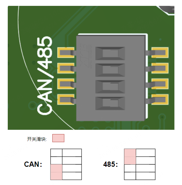
Communication failure | Confirm the communication mode before use; OmniPicker 3 uses CAN-FD by default. To switch modes, adjust the DIP switches:
|
3.4 Other Common Operations
Setting the DIP switches (switching the communication mode):
Prepare a T8 Torx key and remove the four M3×8 screws on the flange end.
Remove the flange to expose the DIP switches on the control board.
Set the DIP switches as required. See Section 4.2, Electrical and Communication Interfaces.
Reinstall the flange and tighten the screws to a recommended torque of 0.6 N·m.
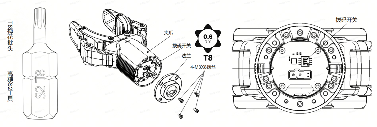
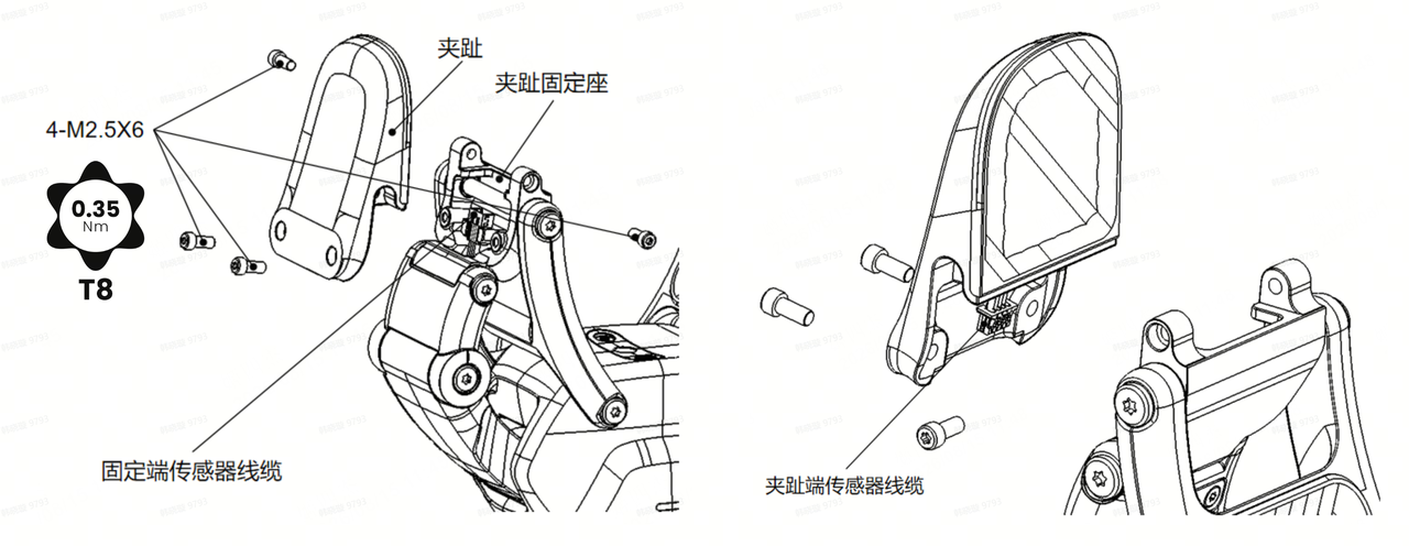
Accessory replacement procedure (accessory replacement generally refers to replacing the fingers, either because a finger is damaged or to fit custom fingers):
Prepare a T8 Torx key and remove the four M2.5×6 screws from the finger.
Take out the finger, take care not to pull the cable loose.
Disconnect the sensor cable connector on the finger from the connector on the fixed end. The finger can then be fully removed.
Take the new or custom finger and connect its sensor cable connector to the connector on the fixed end.
Route the cable neatly into the finger mount. Make sure the cable is not pinched between the finger and the finger mount.
Using a torque wrench with a T8 Torx bit, secure the finger with the four M2.5×6 screws. The recommended tightening torque is 0.35 N·m. Replacement is now complete.
Interface Information
4.1 Mechanical Interface
4.2 Electrical and Communication Interface
Parameter | Spectification |
Operating voltage | 24V (typ) |
Input voltage range | 24~80V |
Operating current | Rated 3A,peak 5A |
Voltage alarm | None |
Communication interface | CAN-FD/RS485, selected by DIP switches; CAN-FD by default |
Switching the communication mode (requires removing the flange cover; see Section 3.4, Other Common Operations)
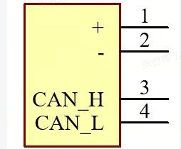
CAN-FD mode: Set switches 1 and 2 to the upper "ON" position, and leave switches 3 and 4 in the lower default position. Connector pin assignment in this mode: 1 — 24V, 2 — GND, 3 — CAN_H, 4 — CAN_L.
RS485 mode: Set switches 3 and 4 to the upper "ON" position, and return switches 1 and 2 to the lower default position. Connector pin assignment in this mode: 1 — 24V, 2 — GND, 3 — RS485_A, 4 — RS485_B.
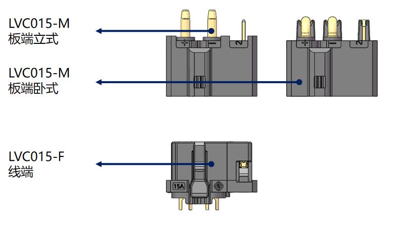
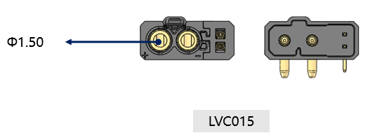
Electrical interface model: Board end LVC015-M, cable end LVC015-F.
 |  |
4.3 OmniPicker 3 Debug Cable Harness
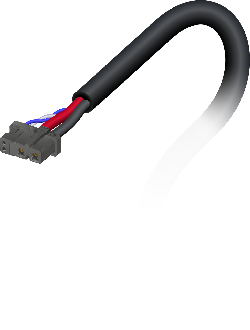
OmniPicker 3 can be connected using the OmniPicker 3 debug cable harness supplied with the gripper. One end of the harness is an LVC015-F (female) connector; the other end splits into a power cable and a twisted pair for CAN-FD or RS485 communication. The harness is 0.2 m long. The LVC015-F (female) connector mates with the LVC015-M (male) connector on the wrist side of OmniPicker 3.
Connect the power cable to a regulated DC power supply. The twisted pair is used to send and receive CAN-FD or RS485 data; the communication mode is determined by the DIP switch settings and can be changed as required during development.
The pin assignment of the OmniPicker 3 debug cable harness is as follows:
LVC015 Pin | Definition | Type | Description | Wire Color | Function |
|---|---|---|---|---|---|
1 | Power+ | Power | DC 24-80V | Red | Power |
2 | Power- | Power | Ground | Black | |
3 | CAN_H/485A | SIG | CAN_H/485A | Blue | Communication |
4 | CAN_L/485B | SIG | CAN_L/485B | White |
Communication Protocols
5.1 Frame Format
CAN-FD
Default configuration: arbitration phase at 1 Mbps (80% sample point) and data phase at 5 Mbps (75% sample point), using the 29-bit extended identifier data frame format. Standard identifiers and remote frames are not supported.
This device supports CAN-FD frame format only. For classic CAN 2.0 frames, the device will:
• not parse the data
• not send any acknowledgment
• not generate error frames
Messages are assembled according to the CAN-FD frame format, with the payload distributed across the arbitration field and the data field: the device ID, project number, register address, and sub-register address are carried in the arbitration field, while the data content is carried in the data field.

The device ID, project number, register address, and sub-register address are carried in the arbitration field; The data content is carried in the data field.
Field | Identifier | Length | Description | Notes |
|---|---|---|---|---|
Arbitration segment standard ID |
| 11 bits | bit[10:6]: Sub-register address
Range: | |
Arbitration segment extended ID |
| 18 bits | bit[17:16]: Lower 2 bits of the register address; together with the lower 6 bits of the standard ID, these form the complete register address byte
bit[15:8]: Fixed at | For device ID, |
Data field |
| n | Data content corresponding to the register |
5.2 Register Description
General register definitions
No. | Register Address | Register Name | Sub-register | Sub-register Name | Register Content | Register Length | Read/Write Permission |
|---|---|---|---|---|---|---|---|
Pn1 |
| Manufacturer Information |
| Sub-register Operation | Read/write all sub-registers under this register; | 48Byte(41Byte) | Read-only |
| Product Model | ASCII string, padded with Example: "OmniPicker 3" | 16Byte | Read-only | |||
| Product Serial Number | ASCII string, fixed length;
"SSCMMVVYMXXXXX" | 14Byte | Read-only | |||
| Hardware Version |
| 4Byte | Read-only | |||
| Software Version |
| 4Byte | Read-only | |||
| Supply Voltage | 32-bit unsigned integer; default 24000 (24.0V); unit mV; | 2Byte | Read-only | |||
| Active DOF | Number of active degrees of freedom. Example: | 1Byte | Read-only | |||
Pn2 |
| Device Information |
| Sub-register Operation | Read/write all sub-registers under this register; | 5Byte | Read/Write |
| Device ID | Default device ID: | 1Byte | Read/Write | |||
| Communication Parameter Configuration |
8-bit unsigned integer, default:
8-bit unsigned integer, default:
8-bit unsigned integer, default:
8-bit unsigned integer, default:
| 4Byte | Read/Write | |||
Pn6 |
| Tactile Sensor (one-dimensional) full data upload |
| Upload data from all sensors | This sub-register takes a query-type parameter and therefore behaves differently from the general sub-register operation.Query (robot → gripper) | Variable; depends on the query type and sensor configuration. Use query type 0x02 (total data length) and 0x04 (total number of reply frames) to obtain the actual values at runtime. | |
| Sensor 0 Data |
| |||||
| Sensor Data | Same format as | |||||
... | |||||||
Pn19 |
| Position Control |
| Sub-register Operation | Read/write all sub-registers under this register; | Single sub-register length × active DOF | Read/Write |
| Target position of joint motor #1 | 16-bit signed integer; default 0; unit: 1/4096 of maximum position Two bytes represent one joint motor; valid values are defined per product Write: sets the target position and returns the current actual position Read: returns the current actual position | 2Byte | Read/Write | |||
... | ... ... | ... ... | ... |
Host Software User Guide
The OmniHand-ToolBox host software is a general-purpose software which supports both OmniHand series and OmniPicker series, use the software to connect to OmniPicker 3 and to control gripper opening and closing, create action sequences, view finger tactile data, and upgrade firmware.
From version 2.7.2 onward, the left-hand navigation pane contains four pages: Main Interface, System Log, Firmware Upgrade, and Settings. These are described in Sections 6.4 to 6.7.
6.1 Operating Environment
Item | Requirement |
|---|---|
Operating System | Windows 10 / 11 (64-bit); Ubuntu 22.04 LTS (64-bit) |
CPU | Intel Core i5 8th gen or later (dual-core 1.5 GHz or above) |
Memory | 8GB or more |
Display | OpenGL 3.3 or later (integrated graphics are sufficient), 1920×1080 or higher resolution recommended |
Communication hardware | Singal-channel or Dual-channel USB to CAN-FD adapter (ZLG or HCAN), with the corresponding CAN-FD driver installed |
Software dependencies | The installation package includes the Qt runtime libraries and the SDK; a separate Qt installation is not required |
The host software communicates with the gripper over CAN-FD. Install the supplied CAN-FD device driver before use.
6.2 Download and Installation
Download the OmniHand-ToolBox software package from the official website.
AGILINK official website link: https://cn.agilink-ai.com/omni-picker3.html
Windows
Download and run the Windows installer, then follow the on-screen instructions to complete the installation. Shortcuts are created on the desktop and in the start menu.
Double-click OmniHand-ToolBox to launch the host software.
Ubuntu 22.04 (.deb package)
Installation — run the following command in the directory containing the .deb file (use the actual file name of your download):
Uninstallation:
sudo apt remove omnihand-toolbox
sudo apt install ./omnihand-toolbox_<version>_<architecture >.deb
Using apt install ./xxx.deb resolves dependencies automatically. After installation, OmniHand-ToolBox appears in the application menu, or can be launched from a terminal by running omnihand-toolbox.
This manual corresponds to host software version v2.7.2. The actual version is shown in the software title bar and in the "Host software version" row of the device information panel on the main interface.
6.3 Login
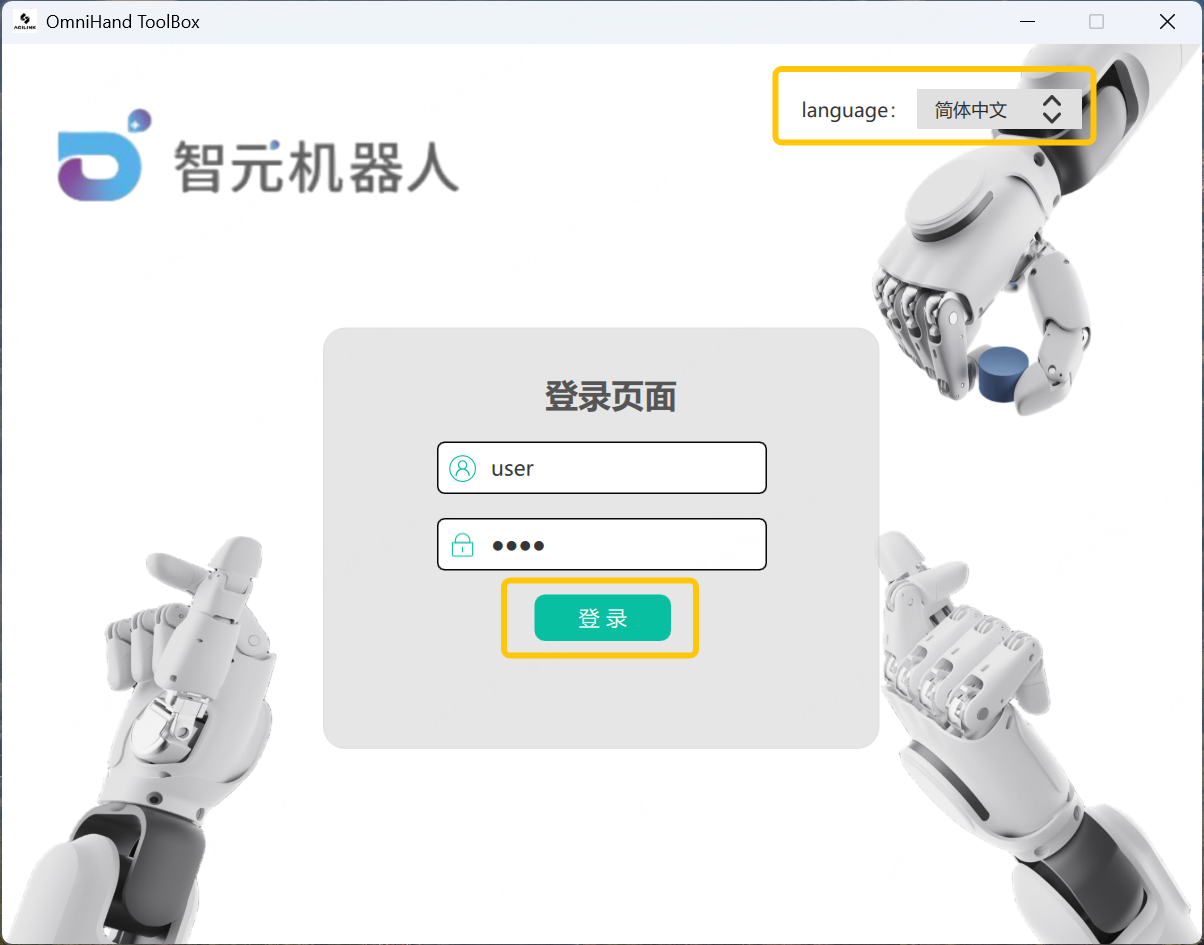
After launching the software, the login screen appears. The username and password are pre-filled as user / user; click Login to enter the main interface — no manual entry is required. The language drop-down list in the upper-right corner switches the interface language. Simplified Chinese and English are currently supported.
6.4 Main Interface
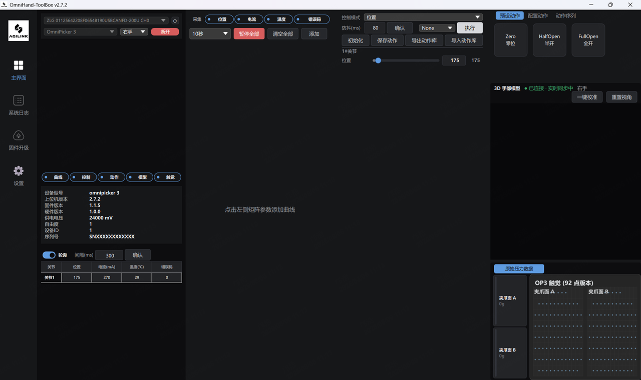
6.4.1 Interface Layout
After logging in, the main interface appears. The window is divided into five areas from left to right(Navigation and four columns of functions):
Navigation pane (left): Main Interface, System Log, Firmware Upgrade, and Settings.
Device column (first column): Quick Connect (see 6.4.2), display toggles, device information (see 6.4.3), and the joint status matrix and polling controls (see 6.4.4).
Curve column (second column): Acquisition toggle and real-time curves (see 6.4.5).
Control column (third column): Control mode, debounce, action presets, and the gripper position slider (see 6.4.6).
Action and tactile column (fourth column): Three tabs — Preset Actions, Custom Actions, and Action Sequences (see 6.4.7) — with the finger tactile display area below (see 6.4.9).
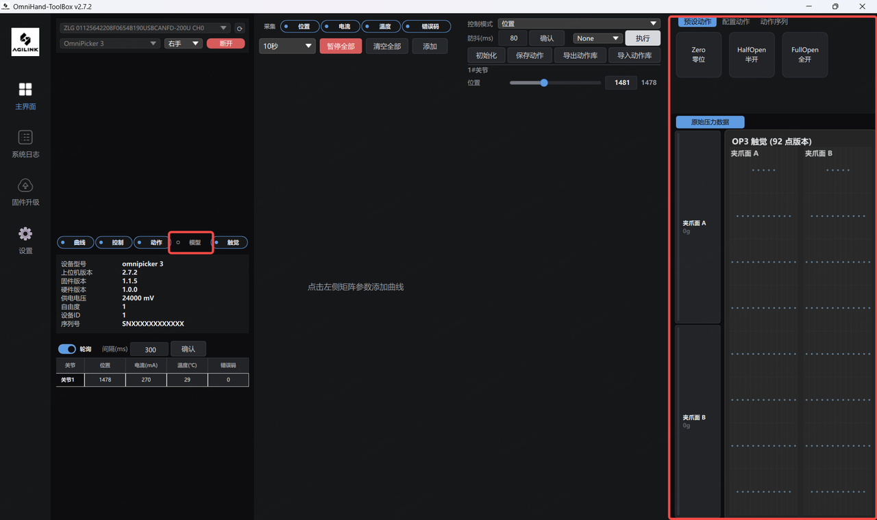
A row of five display toggles is located above the device information panel: Curve, Control, Action, Model, and Tactile. Clearing a checkbox hides the corresponding pane and frees up screen space for the other areas. Note that the Tactile toggle also stops tactile data acquisition when the area is hidden. Since OmniPicker 3 does not provide a 3D model resource, the Model toggle can be left unchecked. On low-resolution displays, it is recommended to keep only the panes you currently need.
6.4.2 Quick Connect
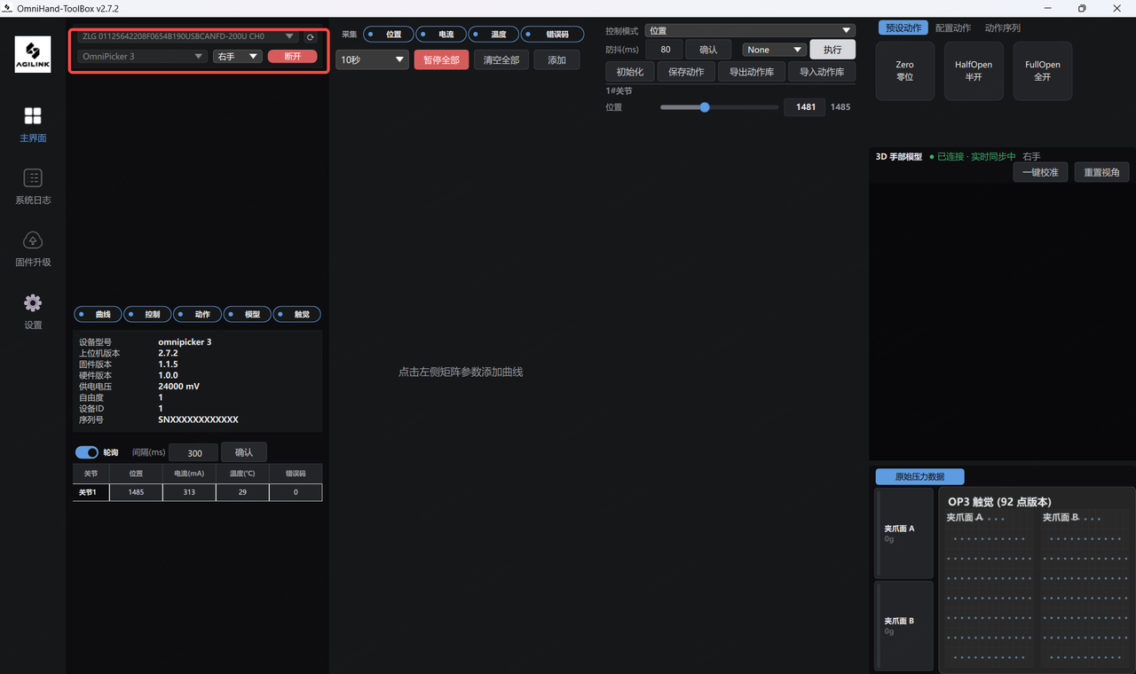
Power on the gripper and connect it to the computer over CAN-FD using a USB-to-CAN-FD adapter.
Select the detected CAN-FD device from the device drop-down list. If No device found is displayed, click the ⟳ button on the right to refresh.
Select the product model (OmniPicker 3). The gripper has no left/right variants, so either option in the left/right hand drop-down list may be selected.
Click Connect. Once the handshake succeeds, the device information panel displays the actual device information, and the button turns red and changes to Disconnect.
For more detailed connection parameters (CAN index, channel, etc.), use the "Settings" page in the navigation pane(see 6.7).
Troubleshooting:
A device is detected but the status remains "Not connected": close and restart the host software; verify that the CAN-FD driver is correctly installed; or check whether the gripper's CAN communication parameters (bit rate and sample point) have been modified — a mismatch with the host software settings will cause the handshake to fail.
No device appears in the drop-down list: check the following in order — whether the CAN-FD adapter driver is installed, whether the device is properly powered, whether the cable harness and connectors are securely seated, and whether the CAN index and channel are correctly selected.
6.4.3 Device Status
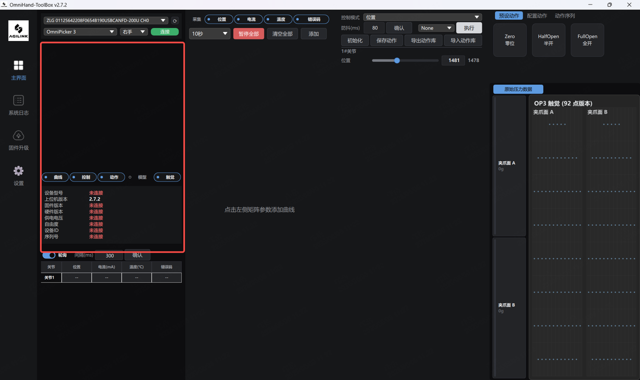
Device information: Displays eight items — device model, host software version, firmware version, hardware version, supply voltage, degrees of freedom, device ID, and serial number. When no device is connected, all items except Host software version display Not connected in red.
OmniPicker 3 becomes operational as soon as it is powered on. No Enable/Disable buttons are provided; The gripper can be controlled directly once connected.
6.4.4 Joint State Matrix and Polling
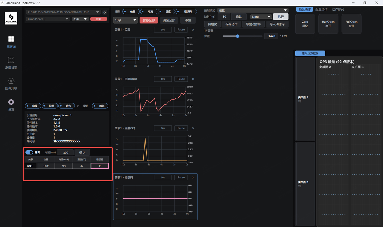
Below the device information panel is the joint status matrix, which displays four real-time values: position, current (mA), temperature (°C), and error code. OmniPicker 3 is a single-axis gripper, so the matrix contains only one row. When no device is connected, all items display "--".
Polling toggle: When enabled, the software reads the above data from the gripper at the configured interval. When disabled, periodic read requests stop; the matrix and curves hold the last values read and are no longer refreshed.
Interval (ms): The polling interval, 300 ms by default. Click Confirm to apply a change. A shorter interval increases bus load; the default value is generally recommended.
Click a parameter cell in the matrix to add that value directly as a real-time curve (see 6.4.5).
6.4.5 Real-Time Curves
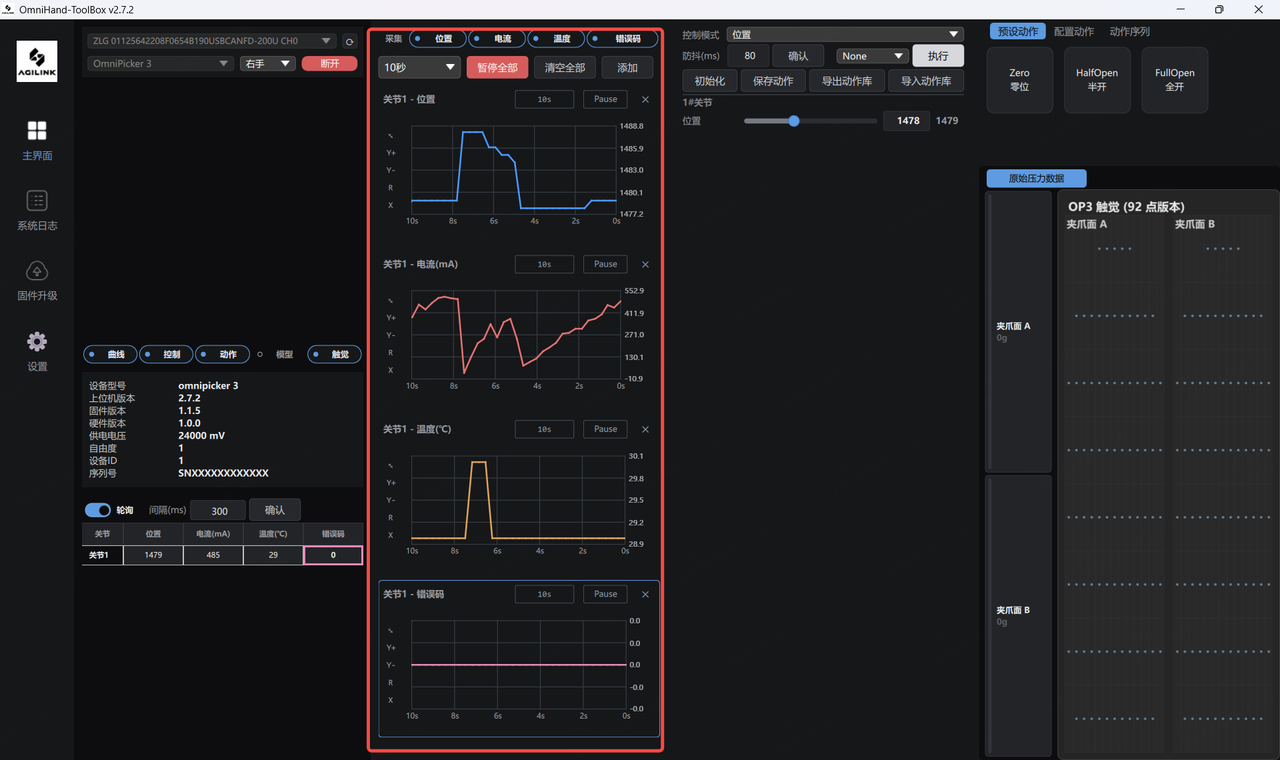
At the top of the curve column are the acquisition toggles: position, current, temperature, and error code. Clearing a checkbox stops updating that value and freezes the corresponding curve.
The next row is the curve toolbar:
Time window drop-down list: The duration shown on the horizontal axis, selectable from several preset values between 1 and 60 seconds.
Pause All / Resume All: Pauses or resumes the refresh of all curves.
Clear All: Clears all plotted curve data.
Add: Opens the Add Curve dialog box. Select a parameter to add a new curve. Available parameters include position, current, temperature, speed, torque, and error code.
When the curve area is empty, the message Click a parameter in the matrix on the left to add a curve is displayed. Each curve has its own set of buttons for pausing, clearing, scaling the vertical axis, resetting the view, and closing it individually. Curves can also be dragged to change their order.
6.4.6 Gripper Control
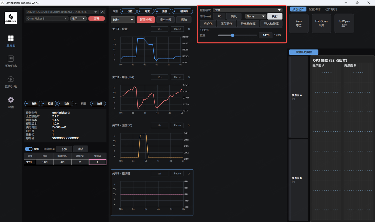
OmniPicker 3 is a single-axis gripper, so the control area contains a single position slider for opening and closing the gripper.
Control mode: Two modes are available. After switching modes, only the parameters required by that mode are displayed and sent.
Mode | Issued Parameters | Description |
|---|---|---|
Position | Position | Default mode. Controls only the target position of the gripper. |
Position + Torque | Position, Torque (mA) | In addition to position, limits the torque current of the gripper motion, in mA. |
Debounce (ms): The minimum interval between position commands sent to the gripper while dragging the slider. Click Confirm to apply the change. When set to 0, every slider change is sent immediately — dragging quickly will generate a large number of messages. When set to a value greater than 0, a position command is sent each time the interval elapses during dragging.
Action preset drop-down list: Lists the available custom actions. Selecting one moves the slider to the position saved in that action. The first item, None, means no action is selected. To delete an action, right-click its row in the list, or click the ✕ that appears on hover.
Execute: Sends the current slider position to the gripper.
Function buttons:
Initialize: Returns the gripper to the initial position it had when the connection was established.
Save action: Saves the current slider position as a custom action. Click the button and enter a name for the action; it will then appear in the Action preset drop-down list. At this point the action exists only within the software — use Export action library to save it to a file.
Export action library: Exports all custom actions in the action presets to a single .json file (see 6.4.8).
Import action library: Reads actions from a .json file and writes them into the action presets. If the file contains actions with the same names as existing ones, a confirmation dialog listing the actions to be overwritten appears before the import.
Position slider: The axis number ("Joint 1#") is shown above the slider; below it are the target value input box and the current feedback value. Drag the slider to control the gripper's opening and closing in real time, or enter a target position in the input box and press Enter to apply it. Positions are given in motor position counts, ranging from 0 to 4095, corresponding to the full travel from closed to fully open. For body parameters such as opening/closing time, see Section 2.3.1.
6.4.7 Preset Actions, Configured Actions and Action Sequence
The top of Column 4 contains three tabs.
Preset Actions
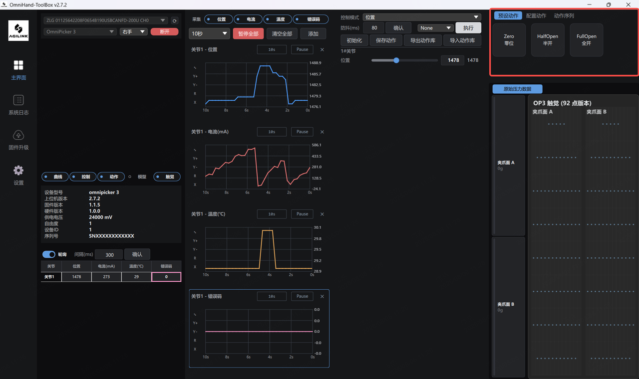
Lists the fixed actions built into the SDK: zero position, half open, and fully open. Click any button to move the gripper quickly to that position. Built-in actions cannot be modified.
Custom Actions
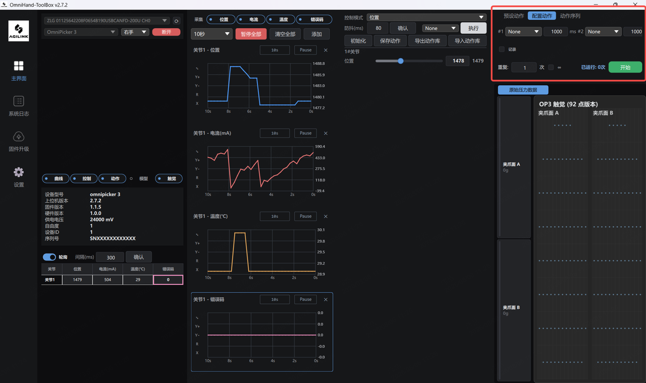
Used to combine several saved actions into a group that runs in a loop.Custom Actions is intended for quick testing and data recording, while Action Sequences is intended for building complete workflows that can be saved and reused.
Click Add to insert a new row. In that row's drop-down list, select an action from the action presets, and enter the interval (in ms) to wait after that action is executed. Rows can be added or removed as needed.
When Record is selected, running data is written to a
CSVfile once the sequence starts; the file path is shown to the right of the checkbox. If it is not selected, the sequence is played back without recording.In the Repeat box, enter the number of loops, or select ∞ for an infinite loop.
Click Start to run the group of actions in a loop, in order. The interface shows the number of loops completed. Click Stop to end the run.
Action Sequences
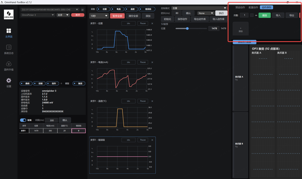
Used to arrange an action sequence consisting of multiple steps:
Add step: Opens a dialog box. Under Select action source, choose a custom action or a built-in preset, and enter the Interval (ms). Once confirmed, the step is appended to the step list.
Repeat / ∞: Sets the number of times the entire sequence repeats, or select ∞ for an infinite loop.
Play / Stop: Runs the sequence in step order.
Import / Export: Saves the current sequence to a file, or loads a sequence from a file.
Clear: Removes all steps from the current sequence. A confirmation dialog appears before the operation.
6.4.8 Action Library File (JSON)
Custom actions in the action list can be saved as a JSON file using Export action library described in 6.4.6, making them easy to reuse later or transfer between computers.
When editing an action file manually, note that the entire file is a JSON array. Each action is a JSON object, objects are separated by commas, and the contents of each object are enclosed in curly braces. Object fields:
name: The name of the action.pos_axis_1: The target position of the gripper. OmniPicker 3 is a single-axis device, so this is the only position field. The value range is the same as that of the position slider described in 6.4.6.
[
  {
    "name": "Zero",
    "pos_axis_1": 0
  },
  {
    "name": "Half-open",
    "pos_axis_1": 2048
  },
  {
    "name": "Fully-open",
    "pos_axis_1": 4095
  }
]
6.4.9 Finger Tactile Display
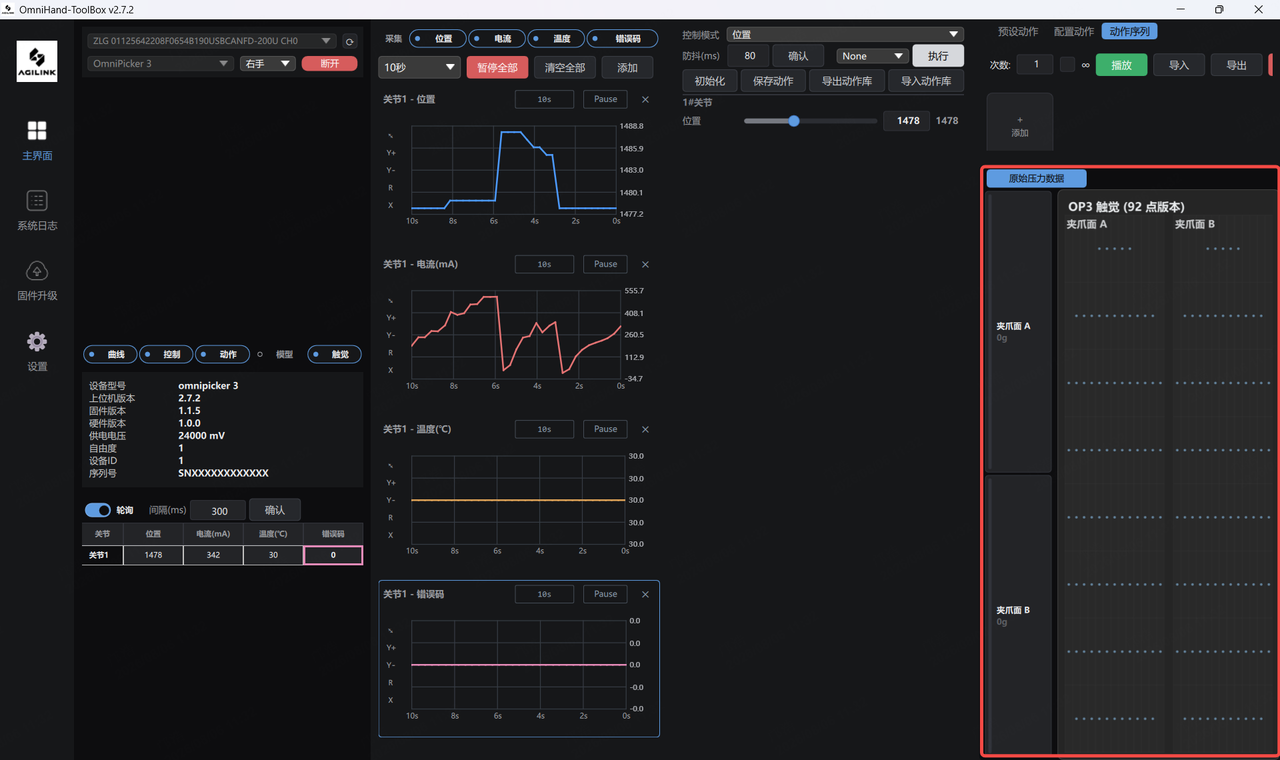
The fingers of OmniPicker 3 are equipped with tactile sensors; see 2.3 for specifications. When the Tactile toggle is selected (selected by default) and the device is connected over CAN-FD, this area displays real-time tactile data:
Region readings (left): Divided into two regions — gripper face A and gripper face B — each showing the total force currently applied to that face (in g). The color bar to the left of each value shifts from blue to red as the force increases, making it easy to see at a glance which face is in contact with an object.
Heat map (right): Displays the force distribution of the two gripper faces side by side. Each cell corresponds to one tactile sensing point on that face. The redder the color, the greater the force at that point; the value is displayed directly on any point under load. The heat map layout matches the actual sensing point arrangement of the installed tactile sensor, and the current point-count version is indicated above it.
When no device is connected or no tactile data is received, the area displays Waiting for OP3 tactile data…. If the display is not needed, clear the Tactile toggle to hide this area.
6.5 System Log
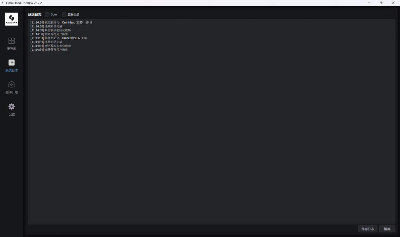
The System Log page records operational information such as model initialization, connection, control mode switching, action execution, and firmware upgrades. New entries scroll automatically to the bottom.
Com: When selected, records detailed information about communication sent and received.
Data recording: When selected, records running data to a
CSVfile. The file path is shown to the right of the checkbox.Save log: Exports the current log contents to a text file.
Clear: Clears the current log display.
6.6 Firmware Upgrade
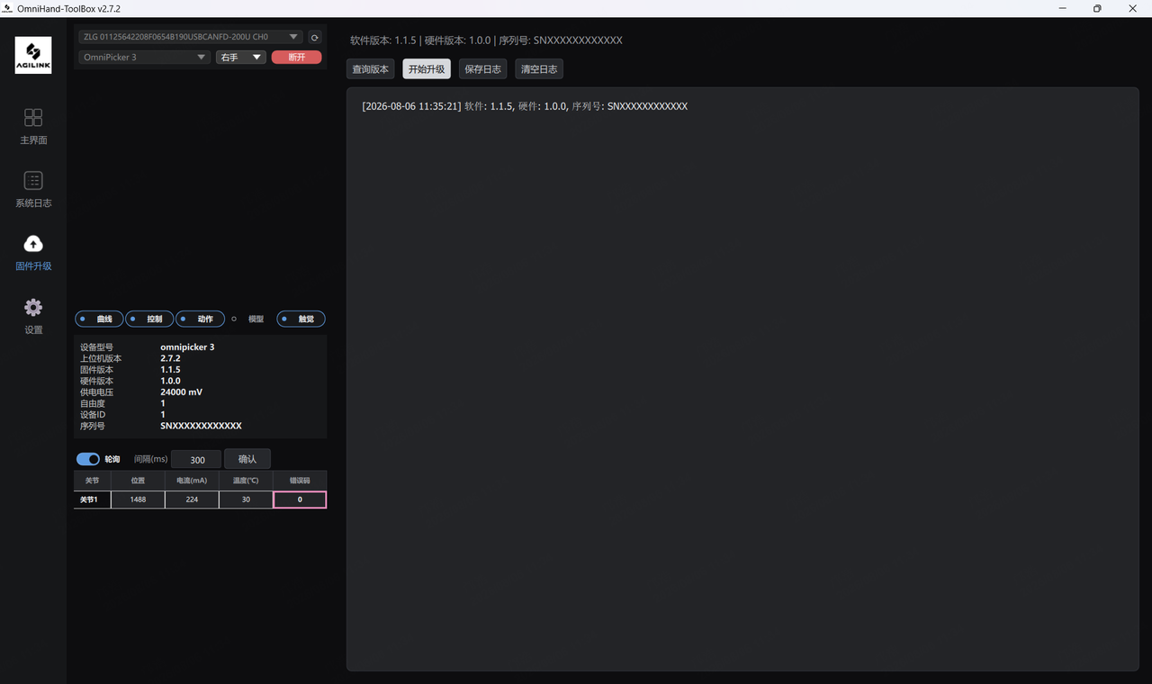
The Firmware Upgrade page shares the connection and device information area in the first column with the main interface. The upgrade operation area is on the right, with a row at the top showing the software version, hardware version, and serial number. To upgrade:
Make sure the device is connected.
Click Query version to view the current software version, hardware version, serial number, and other information.
Click Start upgrade and select the firmware file (.bin) you have downloaded to begin the upgrade.
The upgrade progress is printed to the log. Please wait for the upgrade to complete; on success, the log will show messages indicating that the upgrade has finished and the device is restarting.
If the log shows that the upgrade has failed, click Start upgrade again to retry.
Other buttons: Save log (exports to a .txt file) and Clear log.
The upgrade will not start unless a firmware file has been selected. If the upgrade is interrupted or fails, the failure information remains in the log; reconnect the device as instructed and try again.
6.7 Settings (Device Connection)
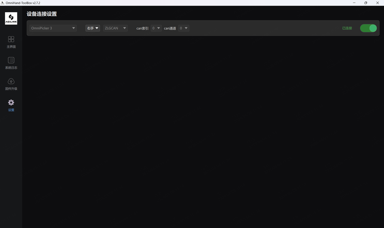
The Settings page provides the full connection parameter configuration:
Product: Select OmniPicker 3.
Hand: The gripper has no left/right variants; Either option may be selected.
Connection type: ZLGCAN and HCAN, with SocketCAN also available on Linux. All of these use CAN-FD. For the communication interfaces of the gripper itself, see 4.2. RS485 connection is not yet available on the host software side and will be supported in a future release.
CAN index / CAN channel: Must match the USB-CAN-FD adapter in use (0 / 0 by default).
The switch on the right connects and disconnects the device. The text to its left shows the current status: Not connected, Connecting…, Connection failed, or Connected.
CAN-FD communication parameters are sent by the software using the fixed values specified in Chapter 5, and do not need to be set manually.
Once the connection is established, the product, connection type, and connection parameters are grayed out and cannot be changed. To modify them, disconnect first.
This manual is continuously updated. For matters not described in other manuals, please refer to the official website or contact the customer service team for information.
