

Important Safety Precautions
This section describes the safety requirements that must be met during the installation and operation of the OmniHand Pro 2025. As the OmniHand Pro 2025 is a semi-finished mechanical product, it is essential to carefully read this manual and fully understand the relevant safety features and potential hazards prior to first use. All relevant personnel must conduct risk assessment before each OmniHand Pro 2025 installation and strictly adhere to all instructions in this manual during operation.
1.1 Notes for Use
Do Not operate or store the OmniHand in any high-temperature or high-humidity environment.
Do Not subject the OmniHand to any excessive mechanical load or shock.
Do Not apply excessive force on fingertips.
Do Not forcibly pull or twist any finger of the OmniHand.
Do Not bring the OmniHand near an open flame or heat source.
Do Not operate or store the OmniHand in a flammable or explosive environment.
Do Not use the OmniHand in any strong electromagnetic fields, such as near high-voltage power lines or high-power machinery.
Do Not use OmniHand to grasp any object that is excessively heavy, overheated, sharp, rough or corrosive.
Do Not expose the OmniHand to any liquid (alcohol, water, beverage, etc.) or dust without proper protection. In case of accidental contact, be sure to power off immediately and contact our after-sales service technicians.
Do Not disassemble the OmniHand without authorization, otherwise, the warranty in the After-Sales Service Commitment will be voided. In case of any malfunction, please contact our After-Sales Service technicians.
Do Not operate any hazardous machinery with OmniHand. The company assume no liability for personal injury or property damage resulting from such actions.
1.2 Risk Assessment
List of Potential Hazards
Mechanical hazards: Crush injuries, abrasions, etc., caused by contact with the OmniHand or any sharp object being held.
Electrical hazards: Electric burns or electric shocks caused by contact with live parts.
High-temperature hazards: Burns caused by prolonged contact with hot surfaces of the OmniHand.
Noise hazard: No significant hazard identified.
Vibration hazard: No significant hazard identified.
Radiation hazard: No significant hazard identified.
Material/substance hazard: No significant hazard identified.
Ergonomic hazard: No significant hazard identified.
Environmental hazard: No significant hazard identified.
1.3 After-Sales Service Commitment
The OmniHand Pro 2025 is covered by a 6-month limited warranty. If any defect due to manufacturing or material flaws occurs after the product is put into use, we would provide necessary spare parts for replacement or repair. The product warranty shall be void if defects result from improper handling, failure to follow the user manual, or unauthorized disassembly of the product. Without prejudice to terms of this warranty, if the product has exceeded its warranty period, we reserve the right to charge customers for the cost of replacement or repair.
Beyond the warranty period, if the device exhibits any defect, we should not be held liable for any damages or losses incurred, including but not limited to production losses or damage to other production equipment.
1.4 Disclaimer
We are committed to continuously improving the product reliability and performance, and therefore reserve the right to make product improvements or upgrade without further notice. We strive to ensure the accuracy and reliability of this manual but shall not be held liable for any errors or omissions it may contain. Defects or malfunctions caused by the following circumstances are not covered within the scope of warranty:
Failure to install, wire or connect other control devices as required by the user manual;
Unauthorized disassembly/assembly of the OmniHand;
Use of OmniHand beyond the specifications or standards stated in the user manual;
Damage resulting from improper transportation;
Damage caused by accidents, impacts, or collisions;
Damage caused by natural disasters, including but not limited to fire, earthquakes, tsunami, lightning strikes, strong winds and floods.
We shall not be held liable for any loss, damage, injury or expense caused by customers violating the disclaimers in this section. Customers are kindly requested to carefully read and agree to this disclaimer before purchasing and using the product.
Product Profile
2.1 Product Overview
OmniHand Pro 2025 is a highly integrated all-round dexterous hand with powerful sensing and exceptional capabilities.
Representing a new class of high-DoF commercial dexterous hands, it combines a compact, lightweight form factor with impressive load capacity, precision, speed, and multi-modal tactile sensing to enable intelligent task execution.
Schematic of Active DOF Motor Sequence for OmniHand Pro 2025
2.2 Features
Human-like dimensions: 19 DoF, only 820g - the smallest, most lightweight and anthropomorphic dexterous hand in its class
Multi-tasking: Optimized configuration for easy manipulation of tools, with a fingertip force of up to 20N
Superior sensing: Multi-modal sensing (position, normal force, tangential force) with 0.1N-level high sensitivity, powered by AI algorithms
2.3 Technical Specifications
OmniHand Pro 2025 | ||
Body Parameters | Weight | ≤ 820g |
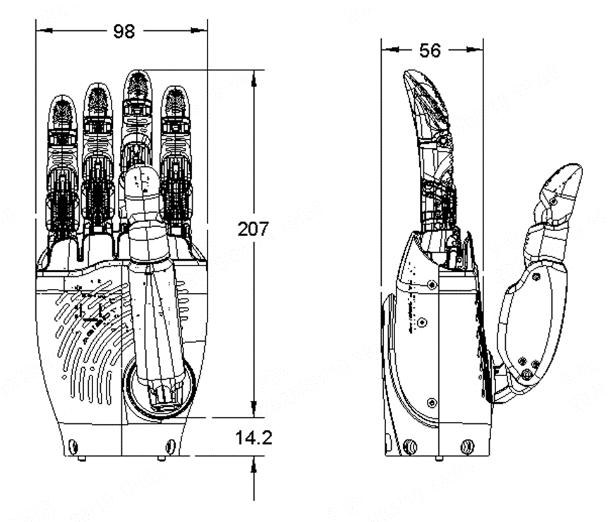
Dimension | 207*98*56 mm | |
Active DoF | 12 | |
Total DoF | 19 | |
Minimum opening/closing time (typical value) | 0.7s | |
Fingertip repetitive positioning accuracy (typical value) | 0.4mm | |
Load capacity | Five-finger grasp force ≥10kg | |
Operating Voltage | 8.3-35.6V | |
Communication interface | CAN-FD | |
Operating Temperature Range | -20~50℃ | |
Online Upgrade | Support OTA online upgrade | |
Tactile sensor | Force sensing type | 3D force on fingertip |
Array resolution | 0.1N | |
Range of sensing | 0~50N | |
Maximum acceptable force (nondestructive) | 1000N | |
[1] The above parameters may vary in different application scenarios and model configurations, depending upon actual conditions.
[2] The product appearance may be upgraded later, please refer to the physical object at that time.
2.4 Range of Joint Angle
Left | Right | ||||
Finger | Joint | Min (°) | Max (°) | Min (°) | Max (°) |
Thumb | thumb_roll_joint | 0 | 42 | -42 | 0 |
thumb_abad_joint | -54 | 0 | 0 | 54 | |
thumb_mcp_joint | -49 | 0 | -49 | 0 | |
thumb_pip_joint | -74 | 0 | -74 | 0 | |
thumb_dip_joint | NA /Coupled joints, coupling relationship reference in the SDK. | ||||
Index Finger | index_abad_joint | -15 | 15 | -15 | 15 |
index_mcp_joint | 0 | 76 | 0 | 76 | |
index_pip_joint | 0 | 85 | 0 | 85 | |
index_dip_joint | NA /Coupled joints, coupling relationship reference in the SDK. | ||||
Middle Finger | middle_abad_joint | -15 | 15 | -15 | 15 |
middle_mcp_joint | 0 | 76 | 0 | 76 | |
middle_pip_joint | 0 | 98 | 0 | 98 | |
middle_dip_joint | NA /Coupled joints, coupling relationship reference in the SDK. | ||||
Ring Finger | ring_mcp_joint | 0 | 79 | 0 | 79 |
ring_pip_joint | NA /Coupled joints, coupling relationship reference in the SDK. | ||||
ring_dip_joint | NA /Coupled joints, coupling relationship reference in the SDK. | ||||
Fifth Finger | pinky_mcp_joint | 0 | 79 | 0 | 79 |
pinky_pip_joint | NA /Coupled joints, coupling relationship reference in the SDK. | ||||
pinky_dip_joint | NA /Coupled joints, coupling relationship reference in the SDK. | ||||
|
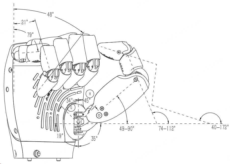
2.5 Product Dimensions
Product Installation Instructions
3.1 Packing List
OmniHand Pro 2025 × 1
USB to CAN-FD communication cable × 1
USB to CAN-FD converter × 1
Power adapter × 1
Product Certificate × 1
3.2 Mechanical Interface
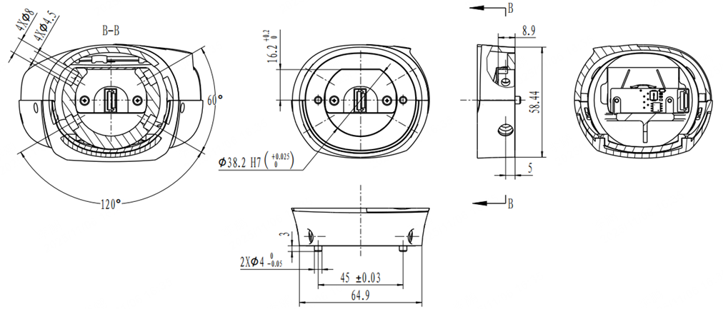
3.3 Installation Instructions
Before installation, please prepare four M4*8 screws and a matching hex key.
Connect the communication cable as illustrated, note the latch orientation.
Insert the robotic arm’s end flange into the OmniHand Pro’s bottom port, secure with four M4 screws. Tightening torque: 1.1–1.5 Nm
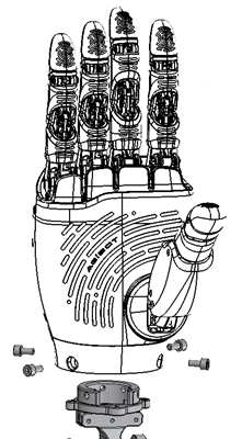
For mounting the OmniHand Pro to other robots, please refer to the mechanical interface diagram and design an adapter flange accordingly.
It is recommended to apply threadlocker to the screws before tightening.
3.4 Electrical and Communication Interfaces
Operating voltage/current: Typical value: 24V/2A. Peak current ≤ 3.5A@24V (< 30s).
Voltage input: 12~28V, maximum withstand voltage 45V (< 1s), undervoltage (8V) and overvoltage (35V) protection disabled, shutdown current < 1mA.
Voltage alarm setting: Configurable undervoltage/overvoltage alarm threshold, with no action upon alarm.
Communication Interface: CAN-FD with 120Ω terminal resistor.
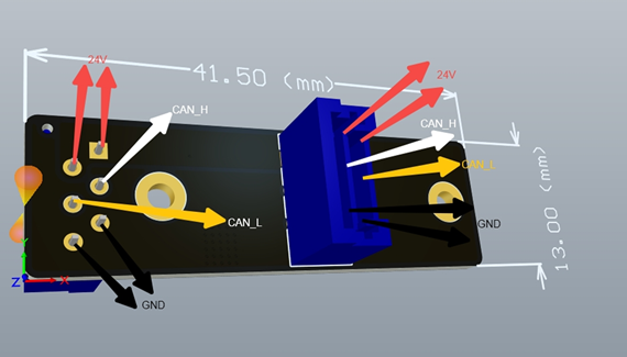
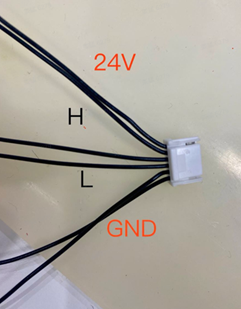
Power Terminal Model: Socket: BM06B-ZESS-TBT, Plug: ZER-06V-S.
Terminal Signal Sequence: 1, 2--24V; 3--CANH; 4--CANL; 5, 6--GND.
|
|
3.5 Caution: Hot-plugging is NOT Supported
When the entire hand is powered on, hot-plugging of power cord or signal cable is not supported and users shall use it properly; in case of malfunction due to unauthorized hot-plugging, the customer should be held solely liable.
Communication Protocols
4.1 Communication Interface
Secondary development based on CAN-FD communication is supported, please check the SDK doc here https://github.com/AgibotTech/OmniHand-Pro-2025
CAN-FD interface, default 1Mbps 80% + 5Mbps 80% extended identifier (29bit) data frame format. Disable standard identifiers and remote frame format;
Control commands follow a question-answer mechanism, some status information can be configured for active reporting, with response timeout 50ms;
If the sender and the responder identifiers match, read/write data is returned;
Extended Frame Definition:
Bit0 - Bit6: Device ID
Bit 7: Read/write flag, 0 for read register operation; 1 for write register operation;
Bit 8~Bit 14: Product ID;
Bit 15: Reserved;
Bit 16~Bit 23: Register address;
Bit 24~Bit 28: Sub-register address;
Byte3 | |||||||
|---|---|---|---|---|---|---|---|
bit31 | bit30 | bit29 | bit28 | bit27 | bit26 | bit25 | bit24 |
x | x | x | Sub-register Address: | ||||
Byte2 | |||||||
bit23 | bit22 | bit21 | bit20 | bit19 | bit18 | bit17 | bit16 |
Register Address: | |||||||
Byte1 | |||||||
bit15 | bit14 | bit13 | bit12 | bit11 | bit10 | bit9 | bit8 |
Reserve | Product ID: | ||||||
Byte0 | |||||||
bit7 | bit6 | bit5 | bit4 | bit3 | bit2 | bit1 | bit0 |
R/W | Device ID: | ||||||
Device ID Definition:
Broadcast Address:
0x00;Default Address:
0x01;Device Address:
0x01~0x7F;Product ID Definition:
Fixed and unmodifiable as per the product definition;
Data Definition: Little-endian;
4.2 Definitions of Register Address and Sub-Address
Read Register will set read/write flag
Bit7to0and Write Register will setBit7to1;Configuration settings written to the register are automatically saved and take effect after a reboot;
Read register commands have unrestricted length and data fields; the default data length is
0with no data content sent.Write register commands must adhere to the specified register length and contain valid data, otherwise, no response will be made.
Limited by sub-register length, maximum one-time configuration supports 32 DOF;
4.3 Definition of General Registers
No. | Register Address | Register Name | Sub-register | Sub-register Name | Register Content | Register Length | Read-Write Permissions |
Pn1 |
| Manufacturer Information |
| Sub-register Operation | All sub-registers under Read/Write Registers; | 48Byte | Read Only |
| Product Model | ASCII string, remaining length padded with Example: | 16Byte | Read Only | |||
| Product SN | ASCII string, fixed length;
| 14Byte | Read Only | |||
| Hardware Version Information | Hardware version information;
| 4Byte | Read Only | |||
| Software Version Information | Software version information;
| 4Byte | Read Only | |||
| Supply voltage | 32-bit unsigned integer; default Valid Range | 2Byte | Read Only | |||
| Active DoF | Example: | 1Byte | Read Only | |||
Pn2 |
| Equipment Information |
| Sub-register Operation | All sub-registers under Read/Write Registers; | 5Byte | Read/write |
| Device ID | Default Device ID: Device ID Address: | 1Byte | Read/write | |||
Pn3 |
| Current Threshold |
| Sub-register Operation | All sub-registers under Read/Write Registers; | Single sub-register length × active DOF | Read/write |
| #1 Joint Motor Current Threshold | 16-bit unsigned integer data; default: 2Byte represents one joint motor; valid range | 2Byte | Read/write | |||
| #2 Joint Motor Current Threshold | 2Byte | Read/write | ||||
... | ... ... | ... | Read/write | ||||
Pn4 |
| Temperature threshold |
| Sub-register Operation | All sub-registers under Read/Write Registers; | Single sub-register length × active DOF | Read/write |
| #1 Joint motor warm-up start threshold | Warm-up start threshold -8-bit unsigned integer data; default value 1Byte represents one joint motor; valid range [50, overtemperature protection threshold - 5] Overtemperature protection threshold - 8-bit unsigned integer; default 1Byte represents one joint motor; valid range [warm-up start threshold + 5, 80] | 2Byte | Read/write | |||
#1 Joint Motor Overtemperature Protection Threshold | |||||||
| #2 Joint motor warm-up start threshold | 2Byte | Read/write | ||||
#2 Joint Motor Overtemperature Protection Threshold | |||||||
... | ... ... | ... ... | ... | ||||
... ... | |||||||
Pn5 |
| Tactile sensor |
| Thumb fingertip sensor | Little endian
Normal force: Force perpendicular to finger surface Tangential force: Force parallel to finger surface Tangential force angle: 0° when fingertip is upward, clockwise rotation; range: 0°~359°. | 48byte | Reserve |
| Index finger tip sensor | ||||||
| Middle finger sensor | ||||||
| Ring finger fingertip sensor | ||||||
| Little fingertip sensor | ||||||
... | ... | ... ... | ... ... | ||||
Pn15 |
| Reserve |
| Sub-register Operation | All sub-registers under Read/Write Registers; | Single sub-register length × active DOF | Reserve |
Pn16 |
| Control Mode |
| Sub-register Operation | All sub-registers under Read/Write Registers; | Single sub-register length × active DOF | Read/write |
| #1 Joint Motor Control Mode | 8-bit unsigned integer data; Extend control modes according to product form definition, default value 0; Lower 3-bit valid
| 1Byte | Read/write | |||
| #2 Joint Motor Control Mode | 1Byte | Read/write | ||||
... | ... ... | ... ... | ... | ||||
Pn19 |
| Position control |
| Sub-register Operation | All sub-registers under Read/Write Registers; | Single sub-register length × active DOF | Read/write |
| #1 Joint Motor Target Position | 16-bit signed integer data; default: 2Byte represents one joint motor; valid values are defined by the product; Write register to set target position and return current position; Read register to get current actual position; | 2Byte | Read/write | |||
| #2 Joint Motor Target Position | 2Byte | Read/write | ||||
... | ... ... | ... ... | ... | ||||
Pn23 |
| Reserve |
| Sub-register Operation | All sub-registers under Read/Write Registers; | Single sub-register length × active DOF | Reserve |
... | ... | ... | ... | ... | ... ... | ... ... | ... |
Pn31 |
| Reserve |
| Sub-register Operation | All sub-registers under Read/Write Registers; | Single sub-register length × active DOF | Reserve |
Pn32 |
| Error Report |
| Sub-register Operation | All sub-registers under Read/Write Registers; | Single sub-register length × active DOF | Read Only |
| #1 Joint Motor Error Information | Actively report current motor error information upon error; 16-bit unsigned integer data; error information defined as follows:
Write | 2Byte | Read/write | |||
| #2 Joint Motor Error Information | 2Byte | Read/write | ||||
... | ... ... | ... ... | ... | ||||
Pn33 |
| Temperature Report |
| Sub-register Operation | All sub-registers under Read/Write Registers; | Single sub-register length × active DOF | Read Only |
| #1 Joint Motor Temperature Information | Write this register to configure and active report cycle time, Unit: ms; 16-bit unsigned integer data; default: Example: actively report joint temperature at 1Hz, send: Read this register to actively get current temperature information, Unit: ℃; 16-bit signed integer data; Example: the current joint temperature is 50°C, report: | 2Byte | Read/write | |||
| #2 Joint Motor Temperature Information | 2Byte | Read/write | ||||
... | ... ... | ... ... | ... | ||||
Pn34 |
| Current Report |
| Sub-register Operation | All sub-registers under Read/Write Registers; | Single sub-register length × active DOF | Read Only |
| #1 Joint Motor Temperature Information | Write this register to configure and active report cycle time, Unit: ms; 16-bit unsigned integer data; default: Example: actively report joint current at 1Hz, send: Read this register to actively get current, Unit: mA; 16-bit signed integer data; Example: if the current joint current is 1,500mA, report: | 2Byte | Read/write | |||
| #2 Joint Motor Temperature Information | 2Byte | Read/write | ||||
... | ... ... | ... ... | ... | ||||
Pn35 |
| Reserve |
| Sub-register Operation | All sub-registers under Read/Write Registers; | Single sub-register length × active DOF | Reserve |
... | ... | ... | ... | ... | ... ... | ... | ... |
Pn47 |
| Reserve |
| Sub-register Operation | All sub-registers under Read/Write Registers; | Single sub-register length × active DOF | Reserve |
4.4 Definition of Manufacturer Configuration Register
Special configuration parameters for different products, such as sensor calibration, finger joint SN, etc;
No. | Register Address | Register Name | Sub-register | Sub-register Name | Register Content | Register Length | Read-Write Permissions |
Pn48 |
| Reserve |
| Sub-register Operation | All sub-registers under Read/Write Registers; | Single sub-register length × active DOF | Reserve |
... | ... | ... | ... | ... | ... ... | ... | ... |
Pn127 |
| Reserve |
| Sub-register Operation | All sub-registers under Read/Write Registers; | Single sub-register length × active DOF | Reserve |
4.5 Firmware Upgrade Register (Reserved)
Host: Host
Device: OmniHand Pro
Byte | Byte | ||||||||||||||
bit31 | bit30 | bit29 | bit28 | bit27 | bit26 | bit25 | bit24 | bit23 | bit22 | bit21 | bit20 | bit19 | bit18 | bit17 | bit16 |
x | x | x | R/W | Sub-register Address: | Register Address: | ||||||||||
Byte | Byte | ||||||||||||||
bit15 | bit14 | bit13 | bit12 | bit11 | bit10 | bit9 | bit8 | bit7 | bit6 | bit5 | bit4 | bit3 | bit2 | bit1 | bit0 |
Reserve | Product ID: | Reserve | Device ID: | ||||||||||||
Parameter ID | Read/write flag bit | Register Address | Register Name | Sub-register | Sub-register Name | Register Content | Register Length | Data Stream |
Pn1 | 1 |
| OTA Data Packet |
| Data Packet | Packet Content | 64Byte | Host -> Device |
Pn2 | 1 |
| OTA-related request command |
| N/C | No response | ||
| OTA upgrade request | 0 - Unsigned 32-bit integer data, firmware length; Note: Firmware length must be 2K-aligned;
| 16Byte | Host -> Device | ||||
| OTA data transfer request |
Note: The packet length is defaulted by 2K; with any packet <2K padded with | 4Byte | Host -> Device | ||||
| OTA completion request | Unsigned 32-bit integer data; reserved default is | 4Byte | Host -> Device | ||||
| OTA reboot request | Unsigned 32-bit integer data; reboot after x delay, | 4Byte | Host -> Device | ||||
| OTA result request | Unsigned 32-bit integer data; reserved default is | 4Byte | Host -> Device | ||||
| OTA exit request | Unsigned 32-bit integer data; | 4Byte | Host -> Device | ||||
Pn3 | 0 |
| OTA-related response command |
| N/C | No response | ||
| OTA upgrade response | Unsigned 32-bit integer data;
| 4Byte | Device -> Host | ||||
| OTA data transfer response | Unsigned 32-bit integer data;
| 4Byte | Device -> Host | ||||
| OTA completion response | Unsigned 32-bit integer data;
| 4Byte | Device -> Host | ||||
| OTA reboot response | Unsigned 32-bit integer data;
| 4Byte | Device -> Host | ||||
| OTA result response | Unsigned 32-bit integer data;
| 4Byte | Device -> Host | ||||
| OTA exit response | Unsigned 32-bit integer data;
| 4Byte | Device -> Host |
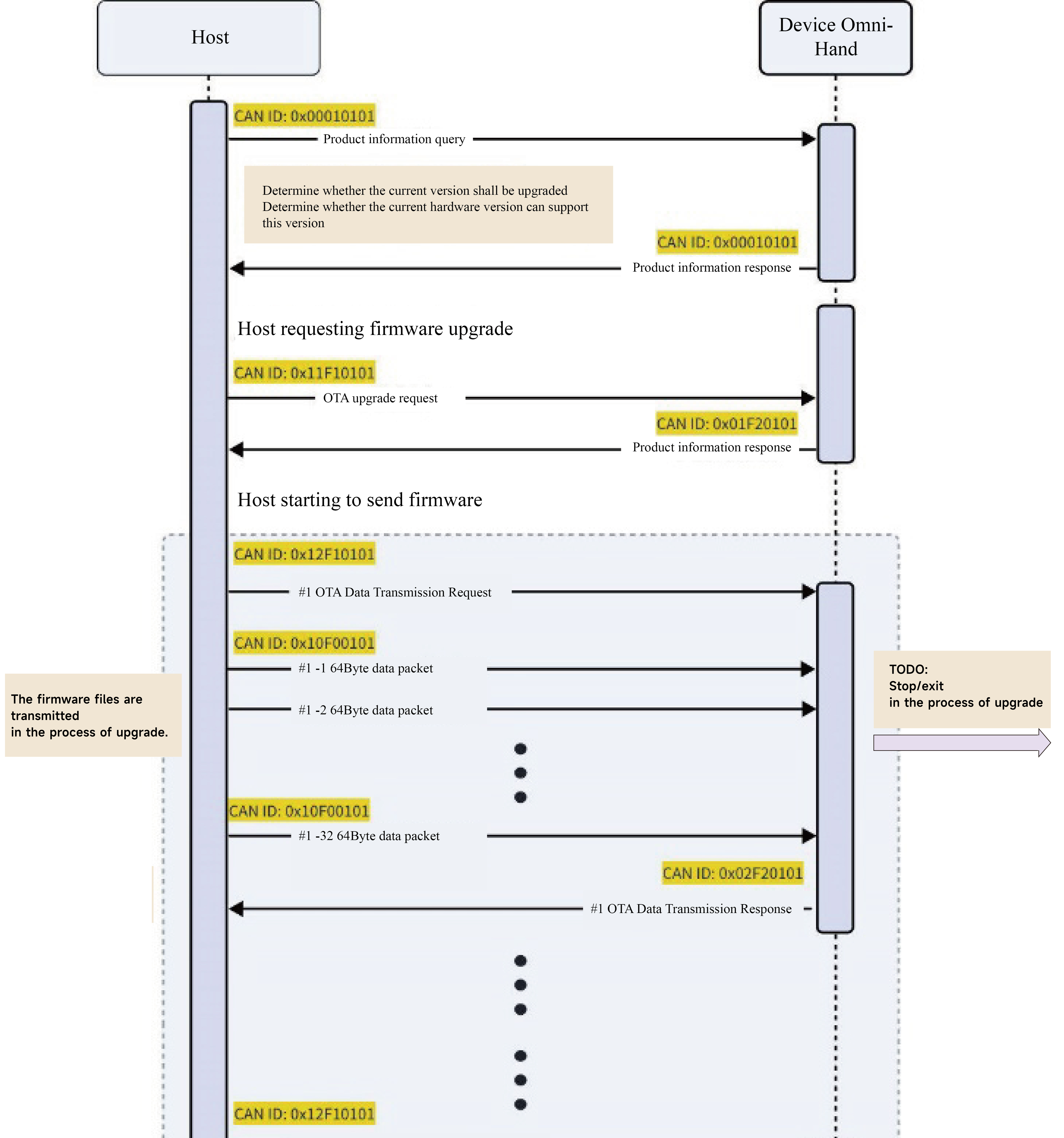
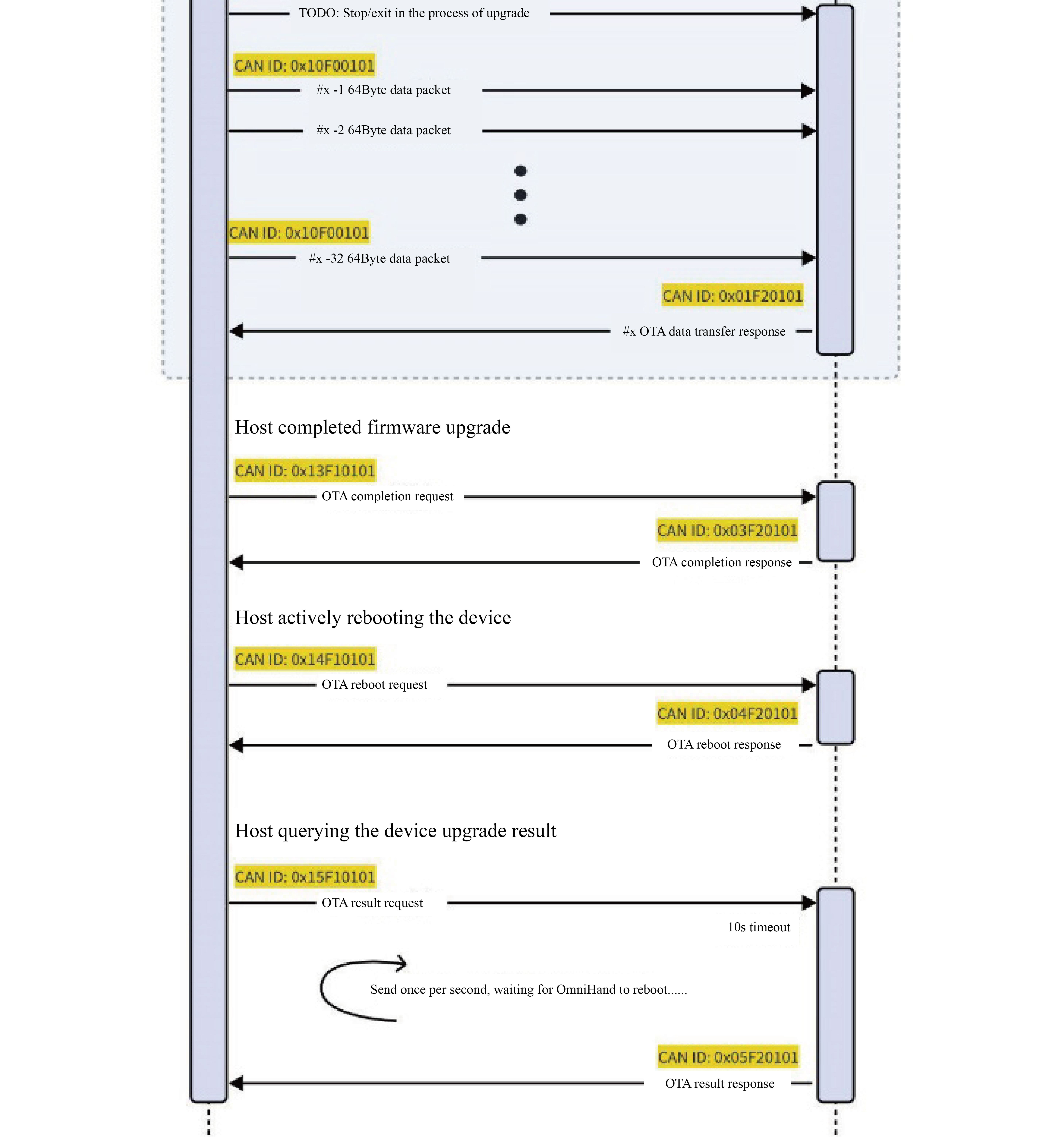
4.5.1 Upgrade Process
4.5.2 Firmware Packet CRC16 Verification Example
class ModbusCRC16 {
public:
    static uint16_t Calculate(const std::vector<uint8_t> &buffer) {
        uint16_t crc = 0xFFFF;
        for (auto data : buffer) {
            crc = (crc >> 8) ^ CRC_TABLE[(crc ^ data) & 0xFF];
        }
        return crc;
    }

private:
    static constexpr uint16_t CRC_TABLE[256] = {
        0x0000, 0xC0C1, 0xC181, 0x0140, 0xC301, 0x03C0, 0x0280, 0xC241,
        0xC601, 0x06C0, 0x0780, 0xC741, 0x0500, 0xC5C1, 0xC481, 0x0440,
        0xCC01, 0x0CC0, 0x0D80, 0xCD41, 0x0F00, 0xCFC1, 0xCE81, 0x0E40,
        0x0A00, 0xCAC1, 0xCB81, 0x0B40, 0xC901, 0x09C0, 0x0880, 0xC841,
        0xD801, 0x18C0, 0x1980, 0xD941, 0x1B00, 0xDBC1, 0xDA81, 0x1A40,
        0x1E00, 0xDEC1, 0xDF81, 0x1F40, 0xDD01, 0x1DC0, 0x1C80, 0xDC41,
        0x1400, 0xD4C1, 0xD581, 0x1540, 0xD701, 0x17C0, 0x1680, 0xD641,
        0xD201, 0x12C0, 0x1380, 0xD341, 0x1100, 0xD1C1, 0xD081, 0x1040,
        0xF001, 0x30C0, 0x3180, 0xF141, 0x3300, 0xF3C1, 0xF281, 0x3240,
        0x3600, 0xF6C1, 0xF781, 0x3740, 0xF501, 0x35C0, 0x3480, 0xF441,
        0x3C00, 0xFCC1, 0xFD81, 0x3D40, 0xFF01, 0x3FC0, 0x3E80, 0xFE41,
        0xFA01, 0x3AC0, 0x3B80, 0xFB41, 0x3900, 0xF9C1, 0xF881, 0x3840,
        0x2800, 0xE8C1, 0xE981, 0x2940, 0xEB01, 0x2BC0, 0x2A80, 0xEA41,
        0xEE01, 0x2EC0, 0x2F80, 0xEF41, 0x2D00, 0xEDC1, 0xEC81, 0x2C40,
        0xE401, 0x24C0, 0x2580, 0xE541, 0x2700, 0xE7C1, 0xE681, 0x2640,
        0x2200, 0xE2C1, 0xE381, 0x2340, 0xE101, 0x21C0, 0x2080, 0xE041,
        0xA001, 0x60C0, 0x6180, 0xA141, 0x6300, 0xA3C1, 0xA281, 0x6240,
        0x6600, 0xA6C1, 0xA781, 0x6740, 0xA501, 0x65C0, 0x6480, 0xA441,
        0x6C00, 0xACC1, 0xAD81, 0x6D40, 0xAF01, 0x6FC0, 0x6E80, 0xAE41,
        0xAA01, 0x6AC0, 0x6B80, 0xAB41, 0x6900, 0xA9C1, 0xA881, 0x6840,
        0x7800, 0xB8C1, 0xB981, 0x7940, 0xBB01, 0x7BC0, 0x7A80, 0xBA41,
        0xBE01, 0x7EC0, 0x7F80, 0xBF41, 0x7D00, 0xBDC1, 0xBC81, 0x7C40,
        0xB401, 0x74C0, 0x7580, 0xB541, 0x7700, 0xB7C1, 0xB681, 0x7640,
        0x7200, 0xB2C1, 0xB381, 0x7340, 0xB101, 0x71C0, 0x7080, 0xB041,
        0x5000, 0x90C1, 0x9181, 0x5140, 0x9301, 0x53C0, 0x5280, 0x9241,
        0x9601, 0x56C0, 0x5780, 0x9741, 0x5500, 0x95C1, 0x9481, 0x5440,
        0x9C01, 0x5CC0, 0x5D80, 0x9D41, 0x5F00, 0x9FC1, 0x9E81, 0x5E40,
        0x5A00, 0x9AC1, 0x9B81, 0x5B40, 0x9901, 0x59C0, 0x5880, 0x9841,
        0x8801, 0x48C0, 0x4980, 0x8941, 0x4B00, 0x8BC1, 0x8A81, 0x4A40,
        0x4E00, 0x8EC1, 0x8F81, 0x4F40, 0x8D01, 0x4DC0, 0x4C80, 0x8C41,
        0x4400, 0x84C1, 0x8581, 0x4540, 0x8701, 0x47C0, 0x4680, 0x8641,
        0x8201, 0x42C0, 0x4380, 0x8341, 0x4100, 0x81C1, 0x8081, 0x4040
    };
};
4.6 General Control Example
Hybrid control example 1:
OmniHand Device ID is 0x01, 12 DoF, with control mode of position-force, which can send target information for 12 joints at once;
Each requested joint bag consists of: Joint ID + control mode + target position + target torque (5 bytes in total);
Each responded joint bag consists of: Joint ID + control mode + actual position + actual torque (5 bytes in total);
Request all current joint control modes to be position-force, target position as 1000 and target torque as 1000;
Respond all current joint control modes to be position-force, actual position as 500 and actual torque as 500;
CAN-FD ID | Length | Data (HEX) | |
Request |
| 64Byte (60Byte valid) |
|
Response |
| 64Byte (60Byte valid) |
|
Hybrid control example 2:
OmniHand Device ID is 0x01, 12 DoF, with control mode of velocity-force control, which can send target information for 12 joints at once;
Each requested joint bag consists of: Joint ID + control mode + target velocity + target torque (5 bytes in total);
Each responded joint bag consists of: Joint ID + control mode + actual velocity + actual torque (5 bytes in total);
Request all current joint control modes as speed-force , target speed as 1000 and target torque as 1000;
Respond all current joint control modes to be velocity-force, actual speed as 1000 and actual torque as 500;
CANFD ID | Length | Data | |
Request |
| 64Byte (60Byte valid) |
|
Response |
| 64Byte (60Byte valid) |
|
Hybrid control example 3:
OmniHand Device ID is 0x01, 12 DoF, with control mode of position-velocity-force, which can send target information for up to 8 joints at once;
Each requested joint bag consists of: Joint ID + control mode + target position + target velocity + target torque (7 bytes in total);
Each responded joint bag consists of: Joint ID + control mode + actual position + actual velocity + actual torque (7 bytes in total);
Request all current joint control modes to be position-velocity-force, target position as 1000, target velocity as 1000 and target torque as 1000;
Response all current joint control modes to be position-speed-force, actual position as 500, actual speed as 1000 and actual torque as 500;
CANFD ID | Length | Data | |
Request |
| 64Byte (56Byte valid) |
|
Response |
| 64Byte (56Byte valid) |
|
Example of gesture control action choreographing:
OmniHand Device ID is 0x01, 12 DoF, setting user-defined gesture 1 to move all joints to Position 1000;
CANFD ID | Length | Data (HEX) | |
Request |
| 24Byte |
|
Response |
| 24Byte |
|
Example of gesture control action executing:
OmniHand Device ID 0x01, 12 DOF, executing the preset action of user-defined gesture 1;
CANFD ID | Length | Data (HEX) | |
Request |
| 0Byte | |
Response |
| 24Byte |
|
Example of cyclic control sequence choreographing:
OmniHand Device ID is 0x01, setting user-defined gesture sequence as execute digit 1 -> delay 1s -> execute digit 2 -> delay 1s -> execute digit 3 -> delay 1s;
CAN-FD ID | Length | Data (HEX) | |
Request |
| 6Byte |
|
Response |
| 6Byte |
|
Example of cyclic control sequence executing:
OmniHand Device ID is 0x01, executing user-defined gesture sequence;
CAN-FD ID | Length | Data (HEX) | |
Request |
| 0Byte | |
Response |
| 6Byte |
|
OmniHand Device ID is 0x01, setting user-defined gesture sequence as execute digit 1 -> delay 1s -> execute digit 2 -> delay 1s -> execute digit 3 -> delay 1s;
CANFD ID | Length | Data (HEX) | |
Request |
| 6Byte |
|
Response |
| 6Byte |
|
Example of cyclic control sequence executing:
OmniHand Device ID is 0x01, executing user-defined gesture sequence;
CANFD ID | Length | Data (HEX) | |
Request |
| 0Byte | |
Response |
| 6Byte |
|
Host Software Instructions
Requirements: Windows 10 and above
5.1 Connection Instructions
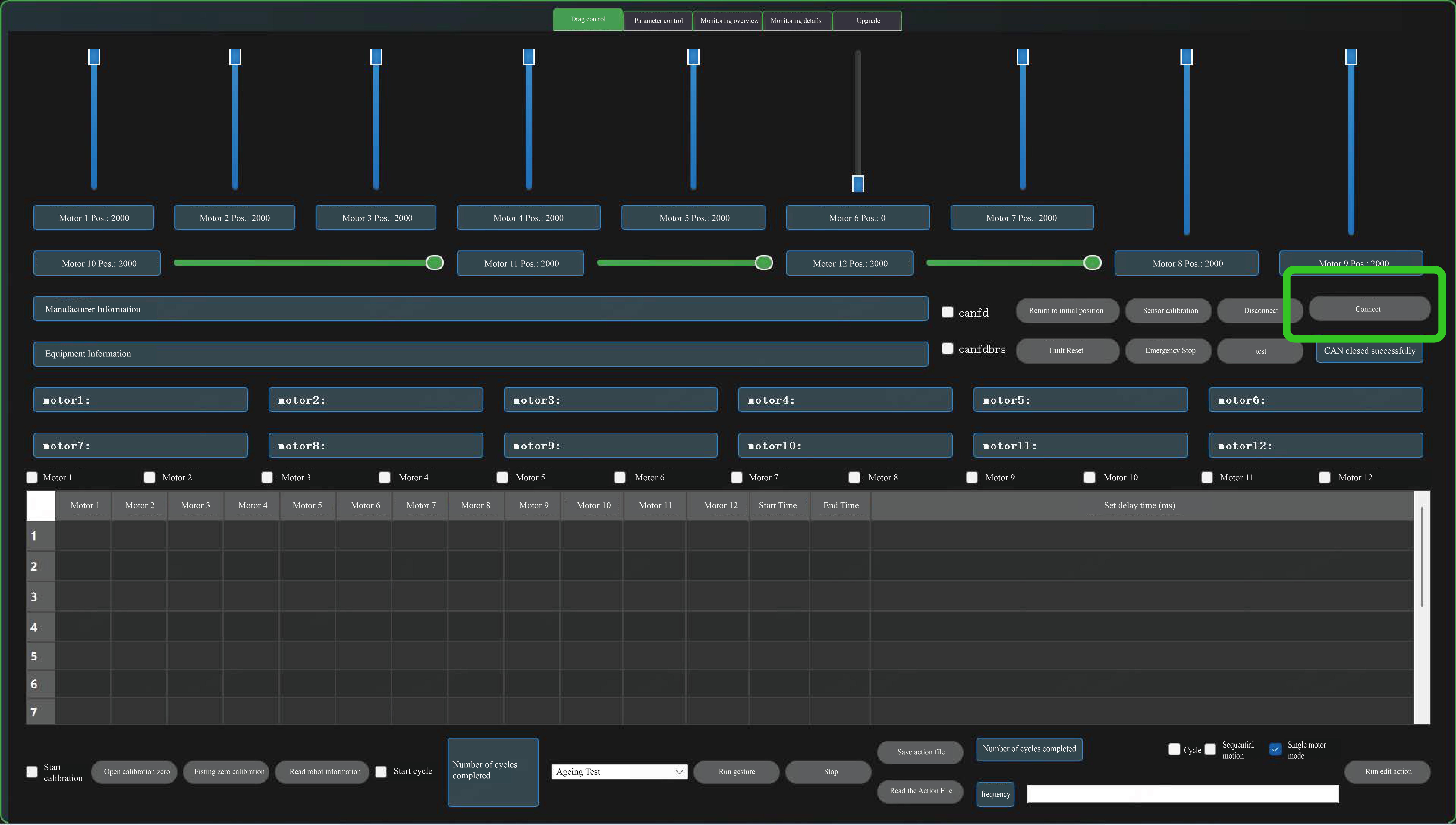
If you click the Connect button, the connection status bar will display "CAN initialized successfully".
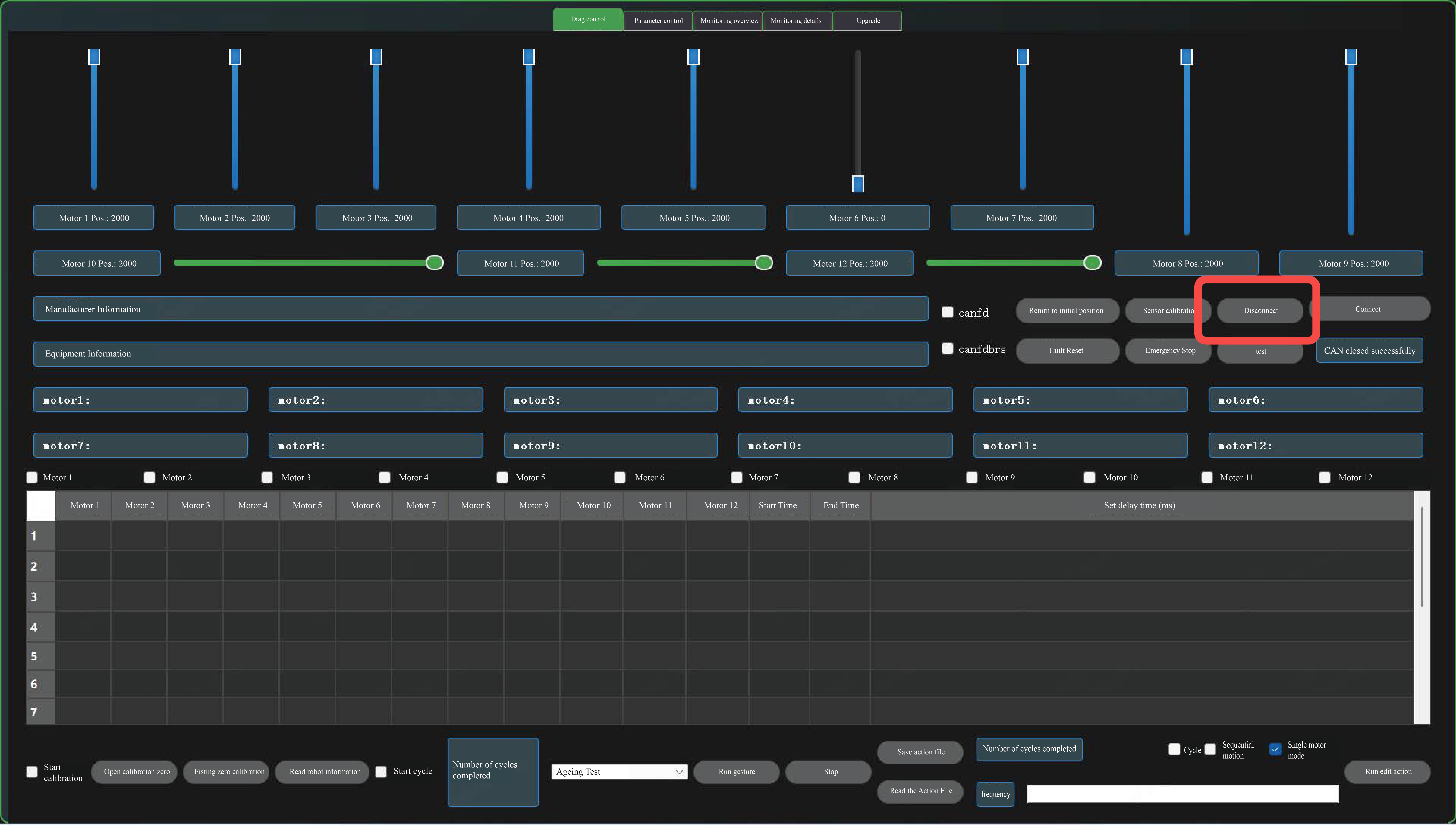
If you click Disconnect, the connection status bar will display "CAN closed successfully".
5.2 Slider Control
5.2.1 Joint Control
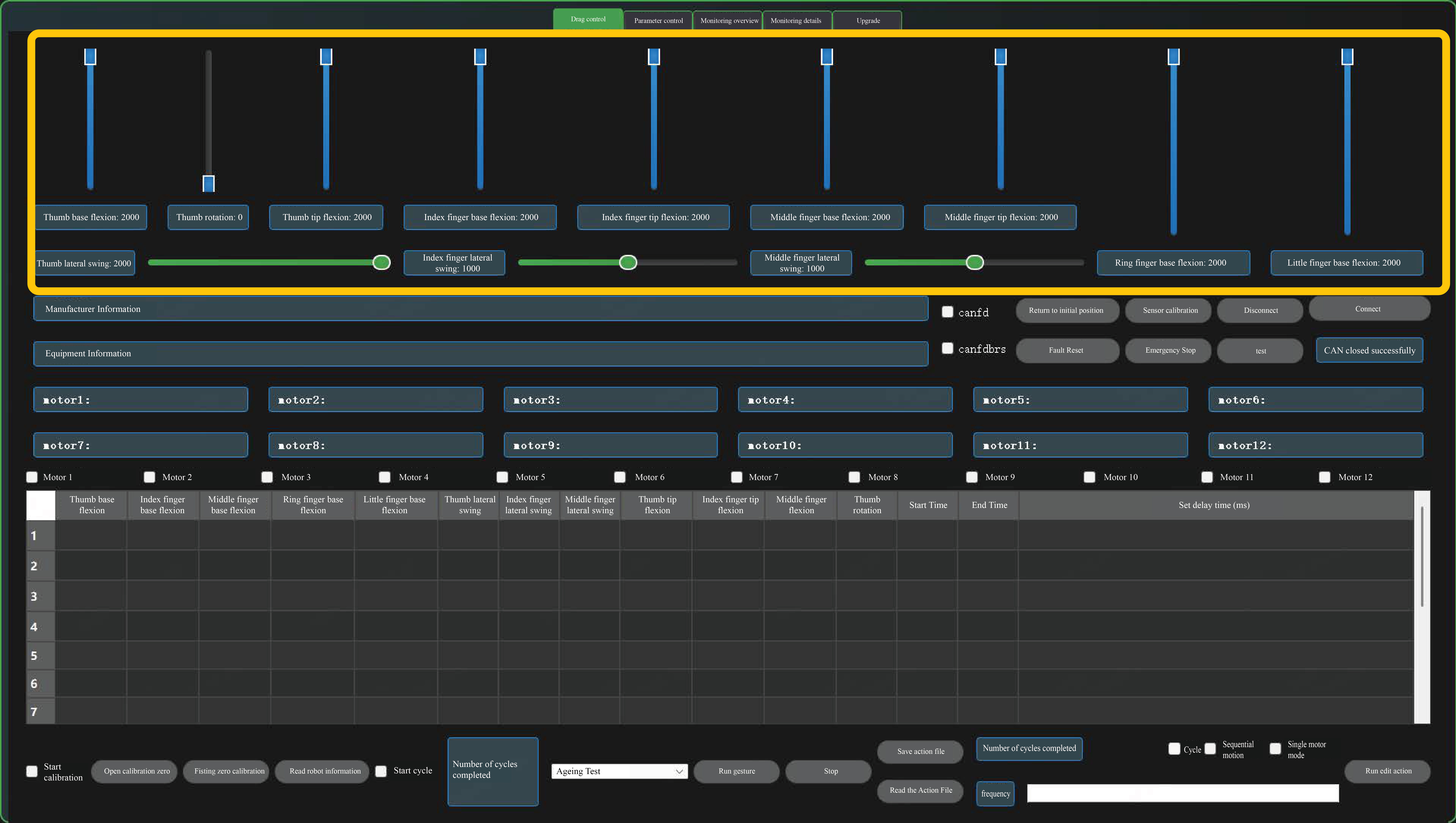
After connecting OmniHand Pro, corresponding joints can be controlled via sliders.
5.2.2 Single Motor Control
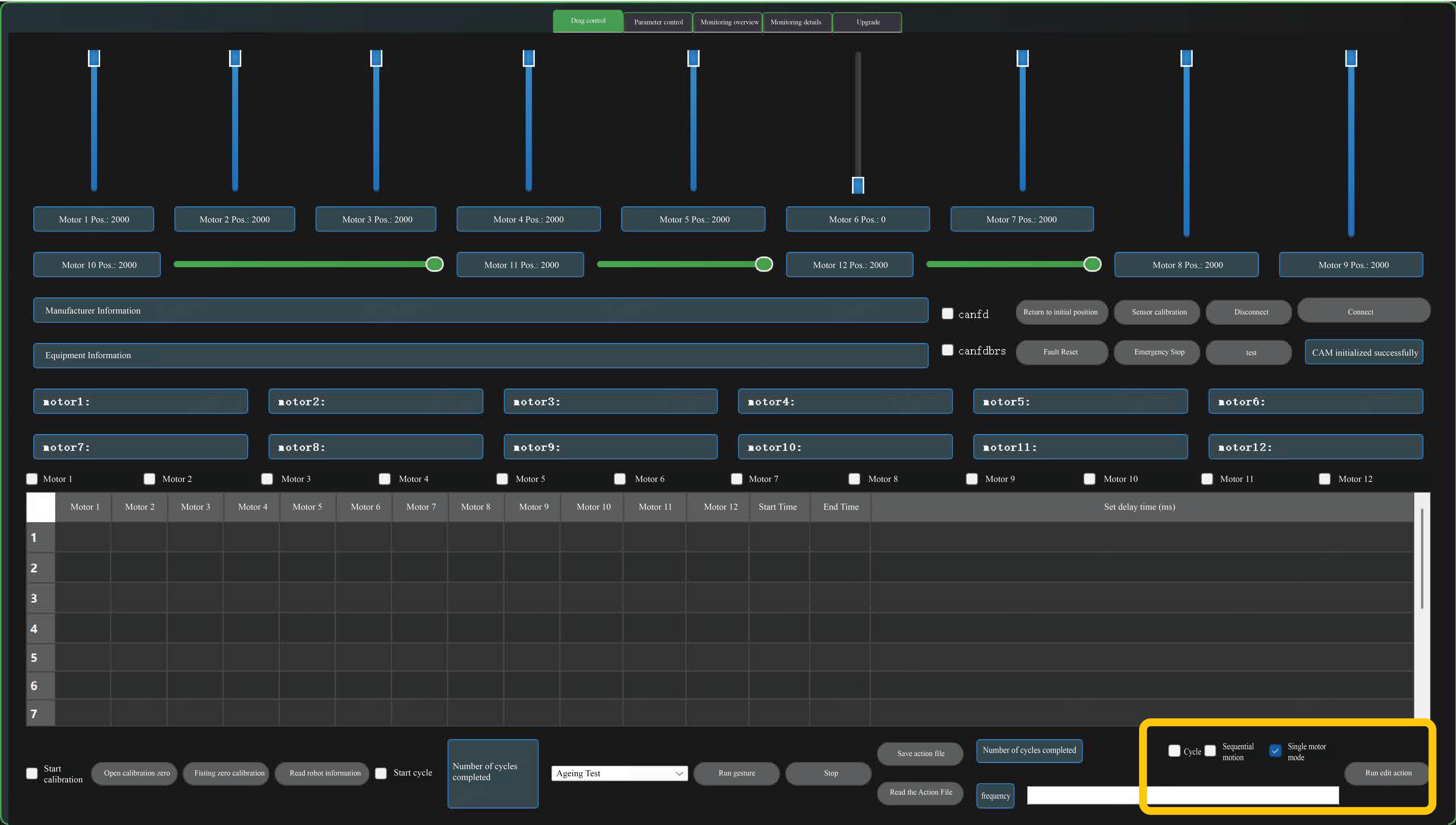
You can check "Single Motor Mode" to switch to individual motor control.
5.3 Control Panel
5.3.1 Joint Control
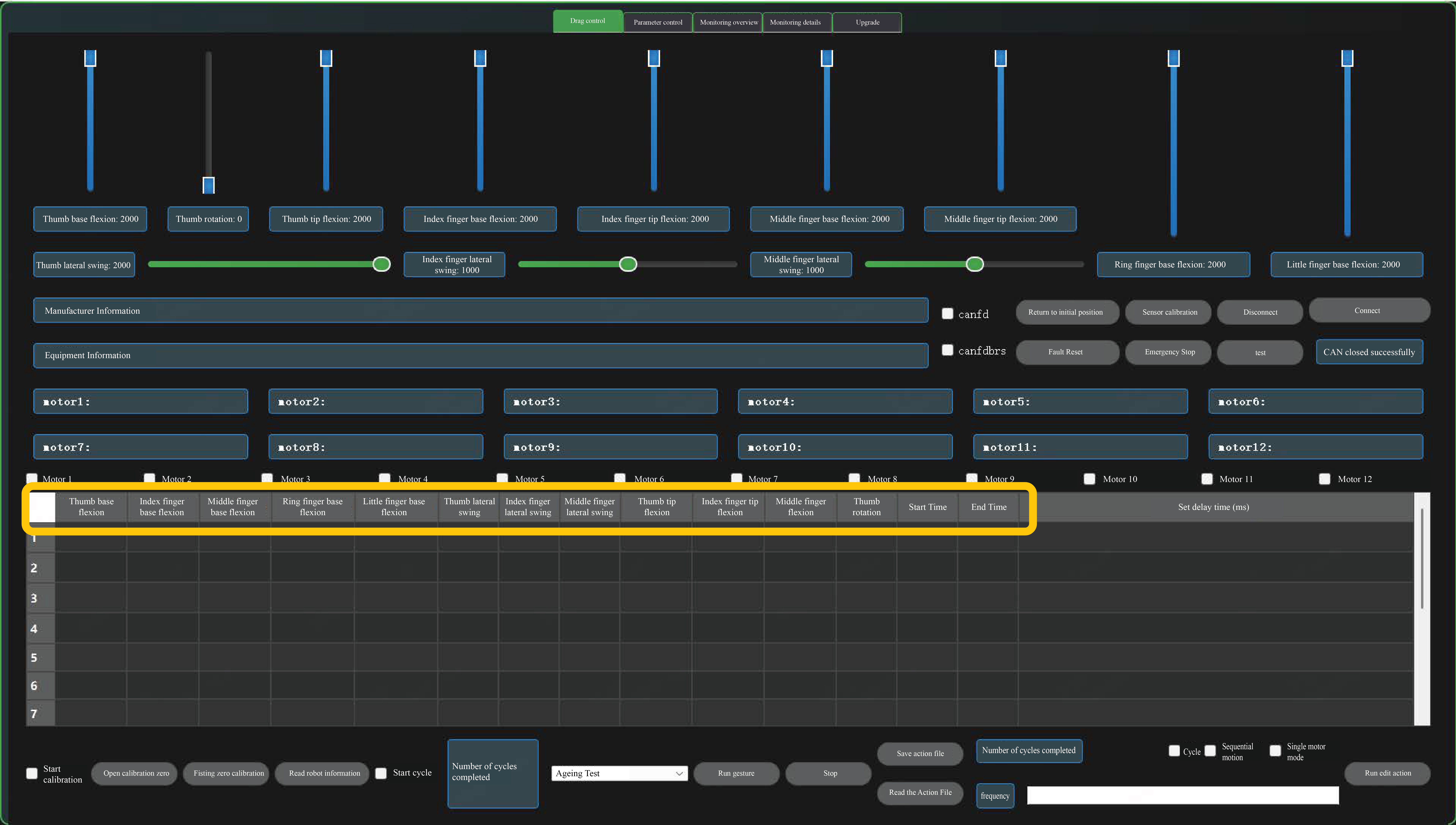
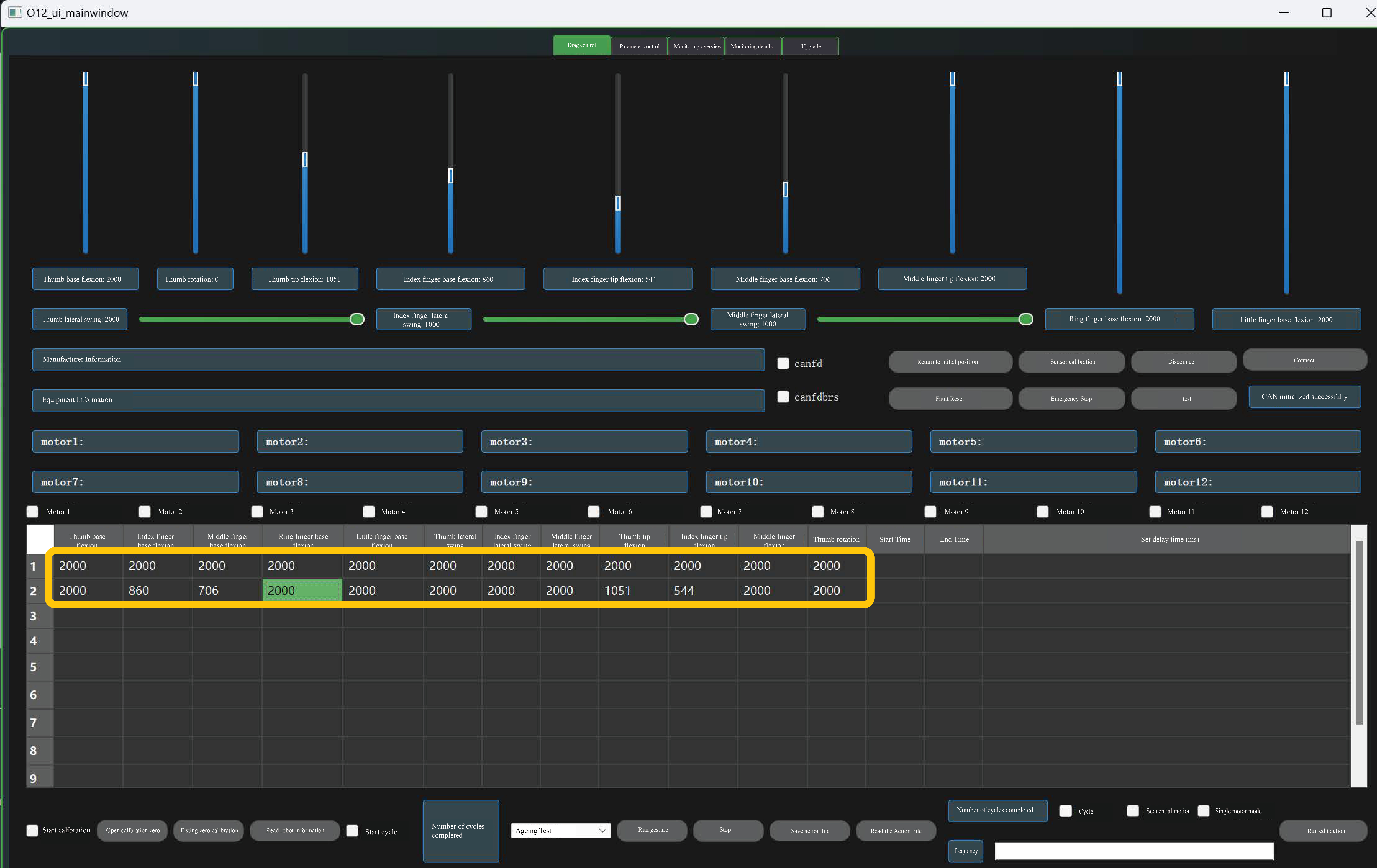
Each row in the table represents an action, where Cells 1 through 12 should be filled with numbers ranging from 0 to 2000; Cells 13 and 14 display the start time and end time of the action execution respectively; Cell 15 is used to set a delay time, which is defaulted to 1000ms if left blank.
If you select the row to be filled with the left mouse button, right-click to bring up the button menu, select "Get Current Position Value" to input the slider's current position into the corresponding cell in the row. You can click the "Run Edit Action" button to execute the action of the selected row;
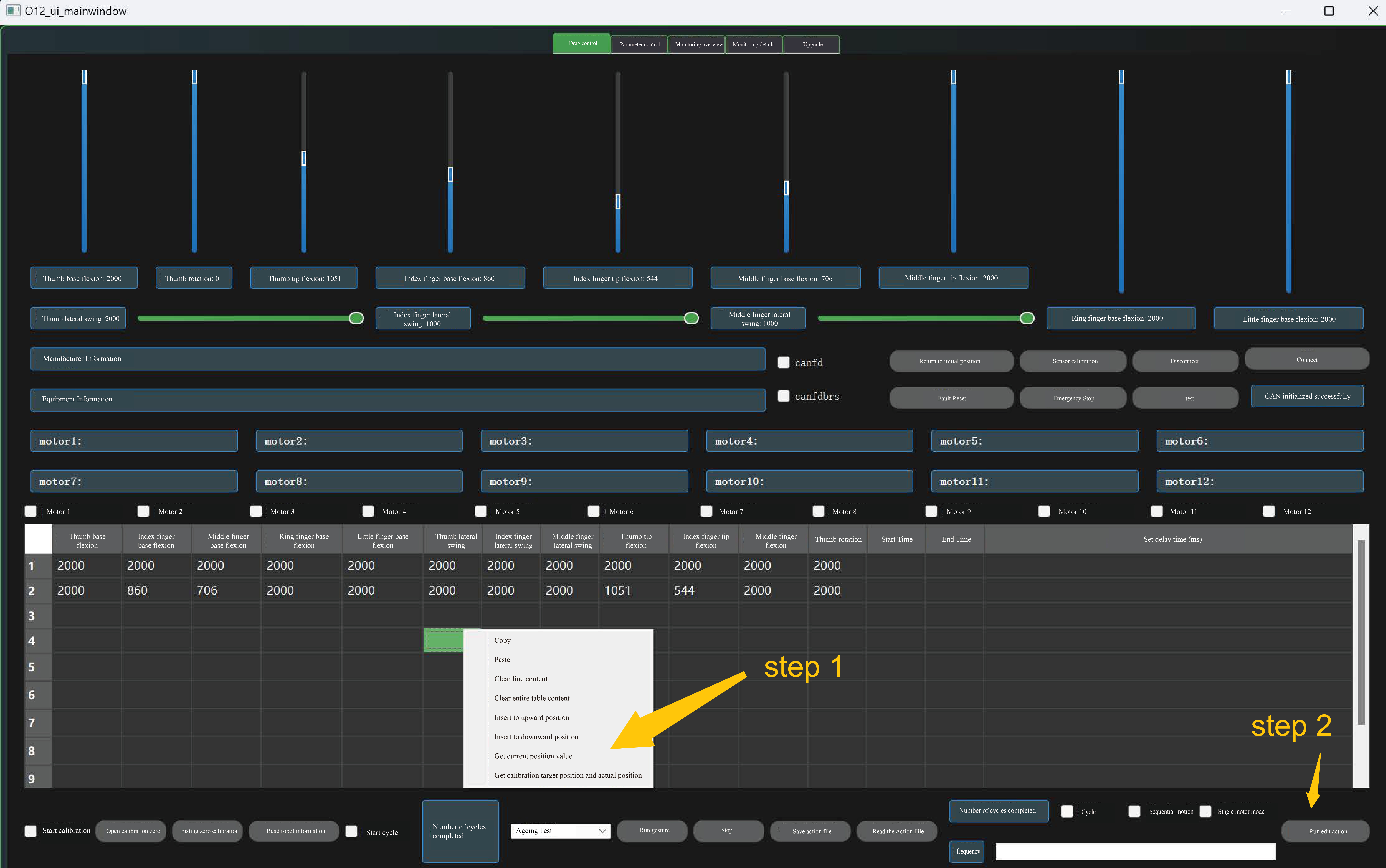
Check "Sequence Motion", click the "Run Edit Action" button to execute all actions from the first row to the last;
Check "Loop", enter a number >0 in the count field, click the "Run Edit Action" button to cyclically execute all actions from the first row to the last for specified count;
5.3.2 Single Motor Control
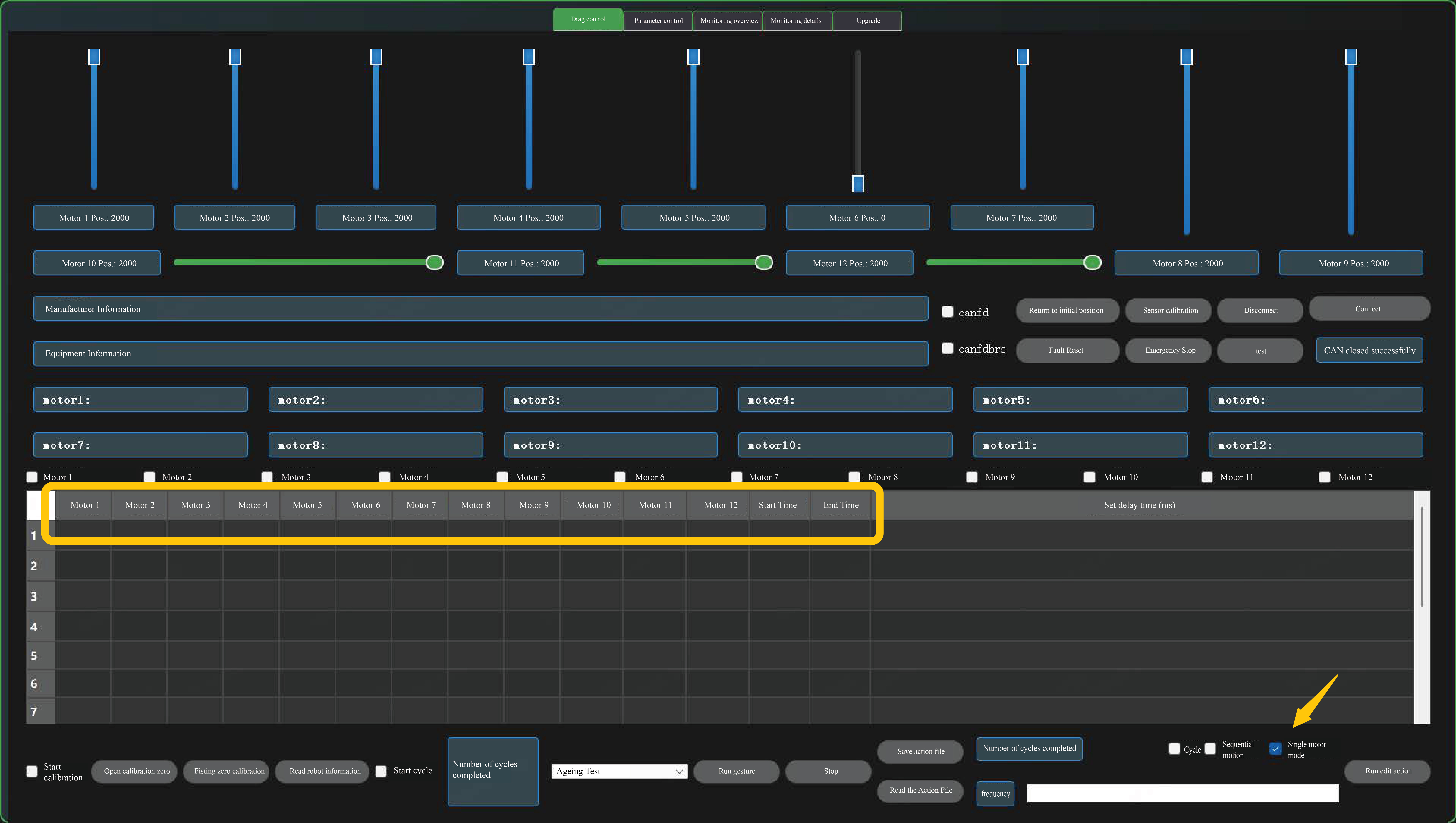
Check the "Single Motor Mode" to switch the table to the corresponding motor title;
First, check the box of motors to be controlled, e.g., Motor 1. In the corresponding Motor 1 column of the table, enter the target position value (0-2000), select the motion row, click the "Run Edit Action" button, then the corresponding motor will move to the input target position. For example, if you select the first row with the left mouse button and click the "Run Edit Action" button, Motor 1 will move to Position 2000.
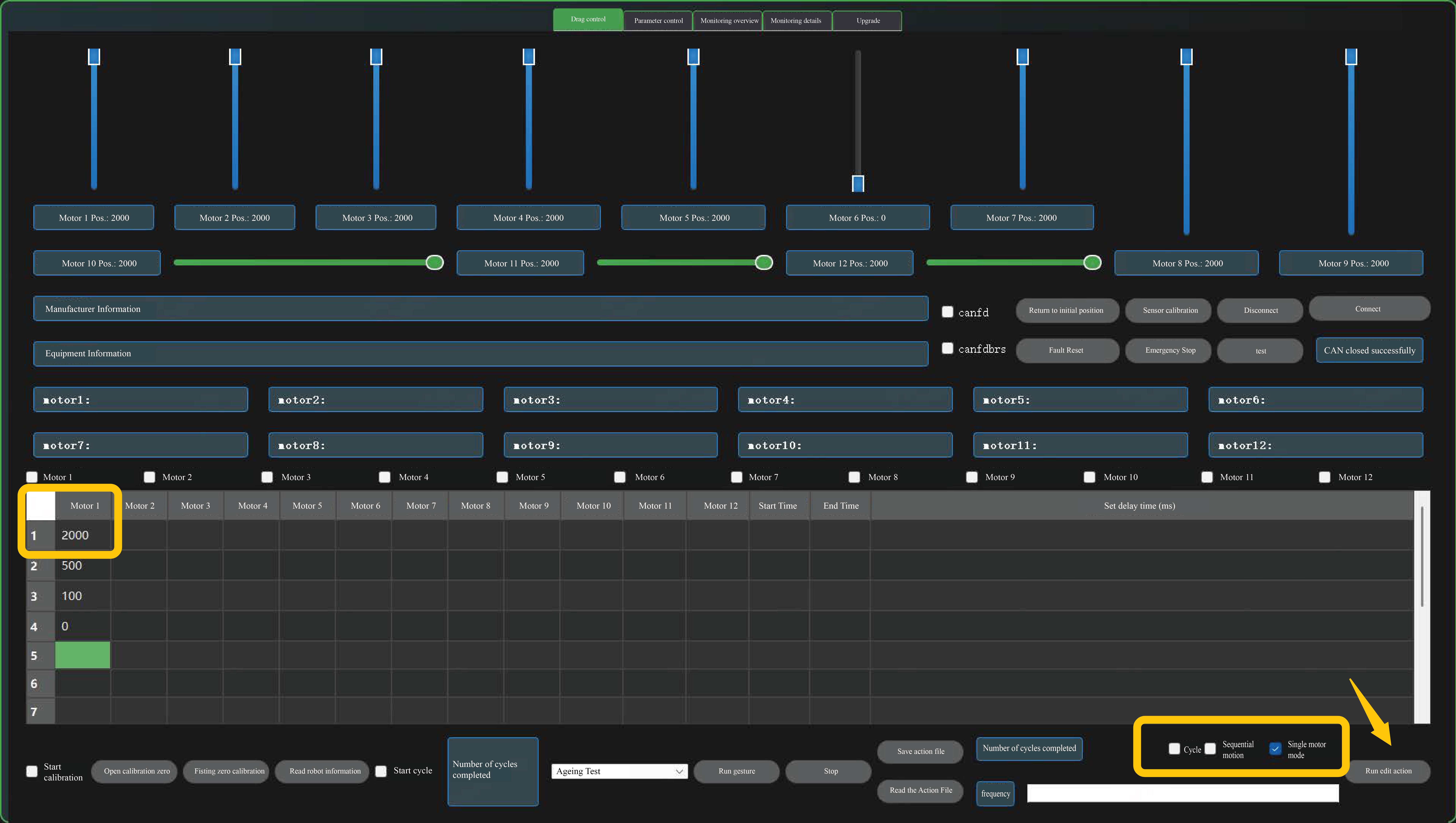
Sequential motion, with the cycle identical to the table's joint control.
5.3.3 Action Record
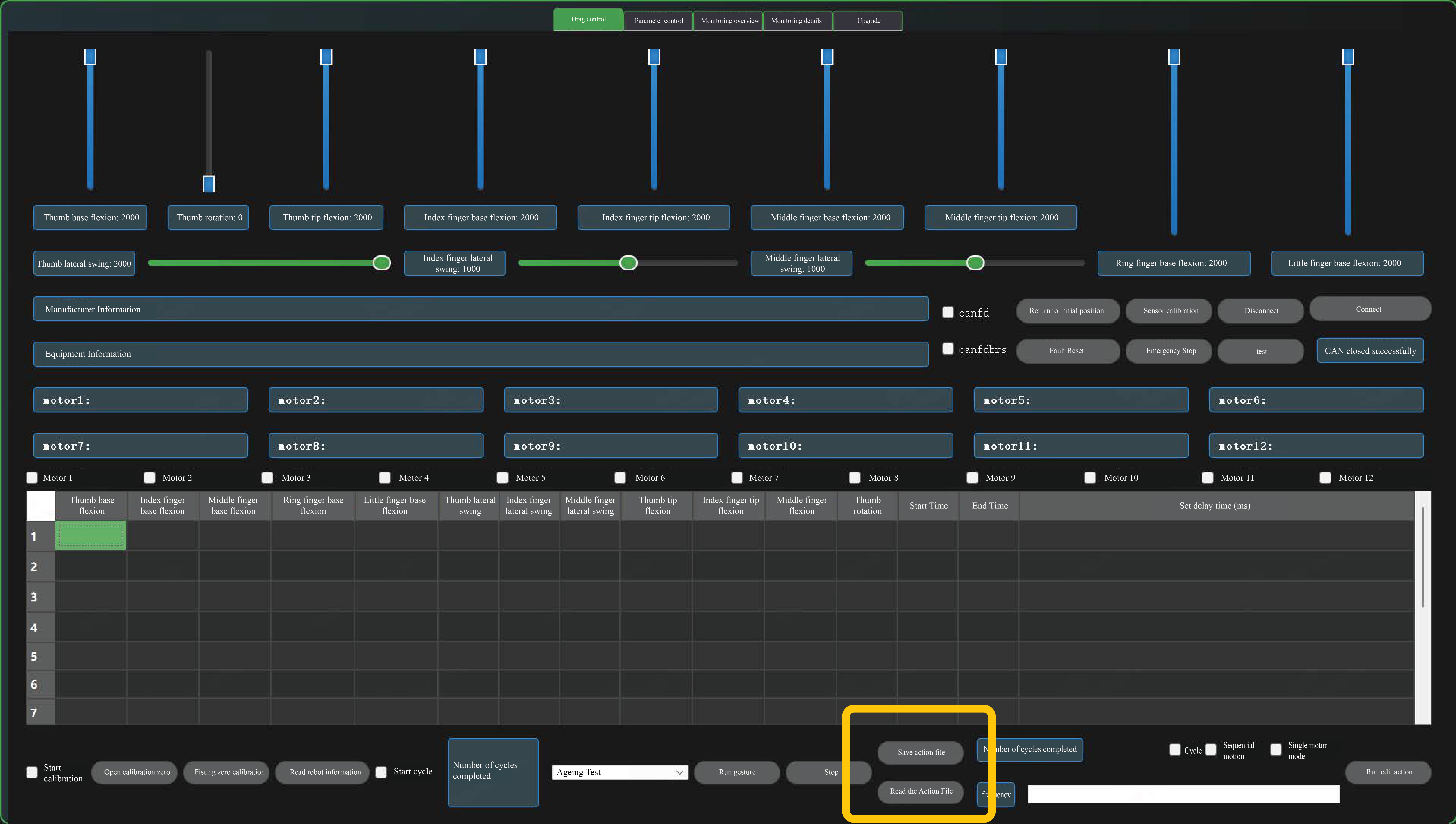
You can click the "Save Action" button to save position data from the table to a .txt file;
Click the "Read Action" button to display and execute saved action files in the table;
5.3.4 Emergency Stop
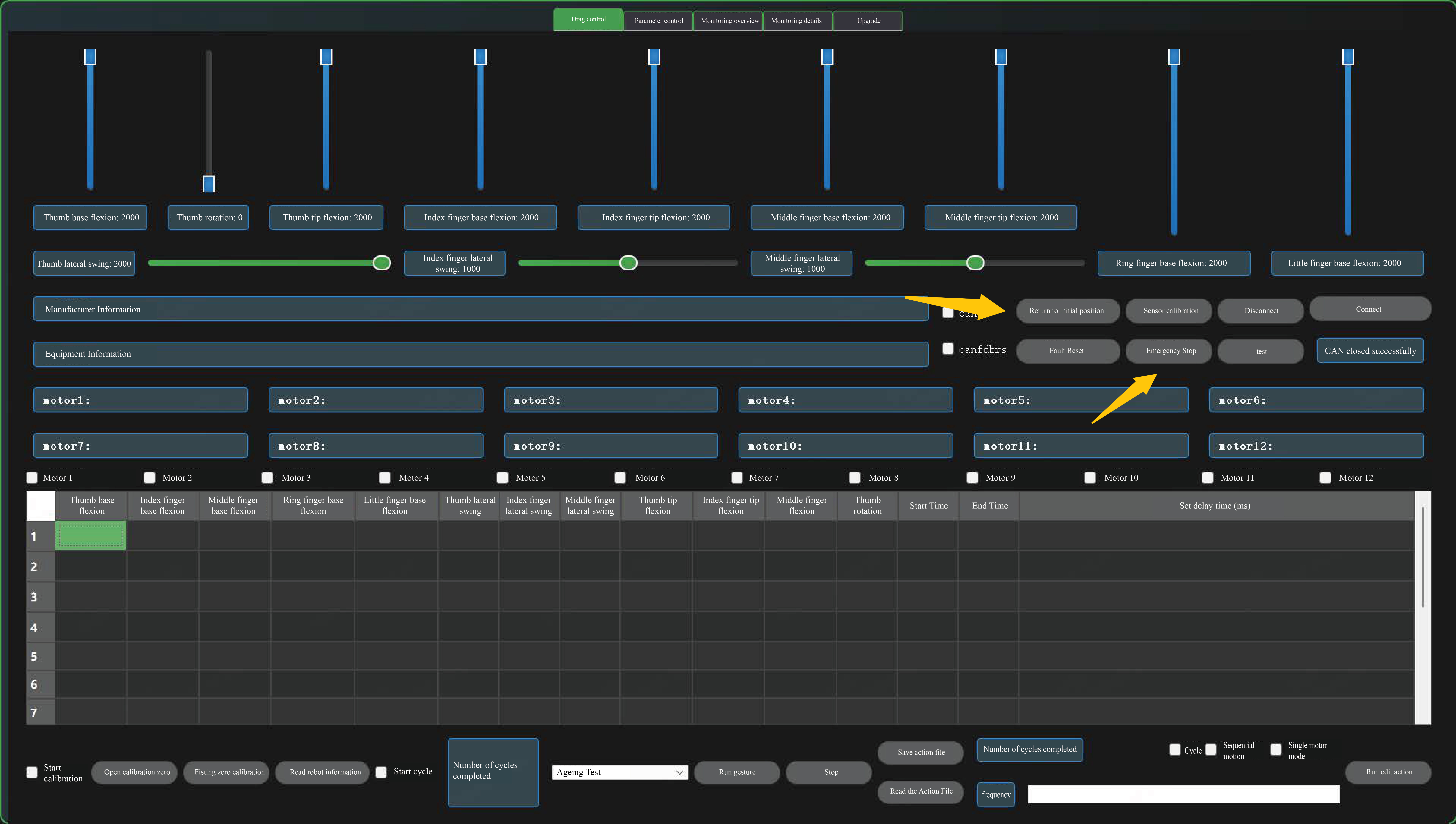
In the process of cycling, click the "Emergency Stop" button to stop the cycle. The "Reset to Initial Position" button can open the hand; "Fault Reset" will send a fault reset command and release the emergency stop lock.
5.4 Preset Action
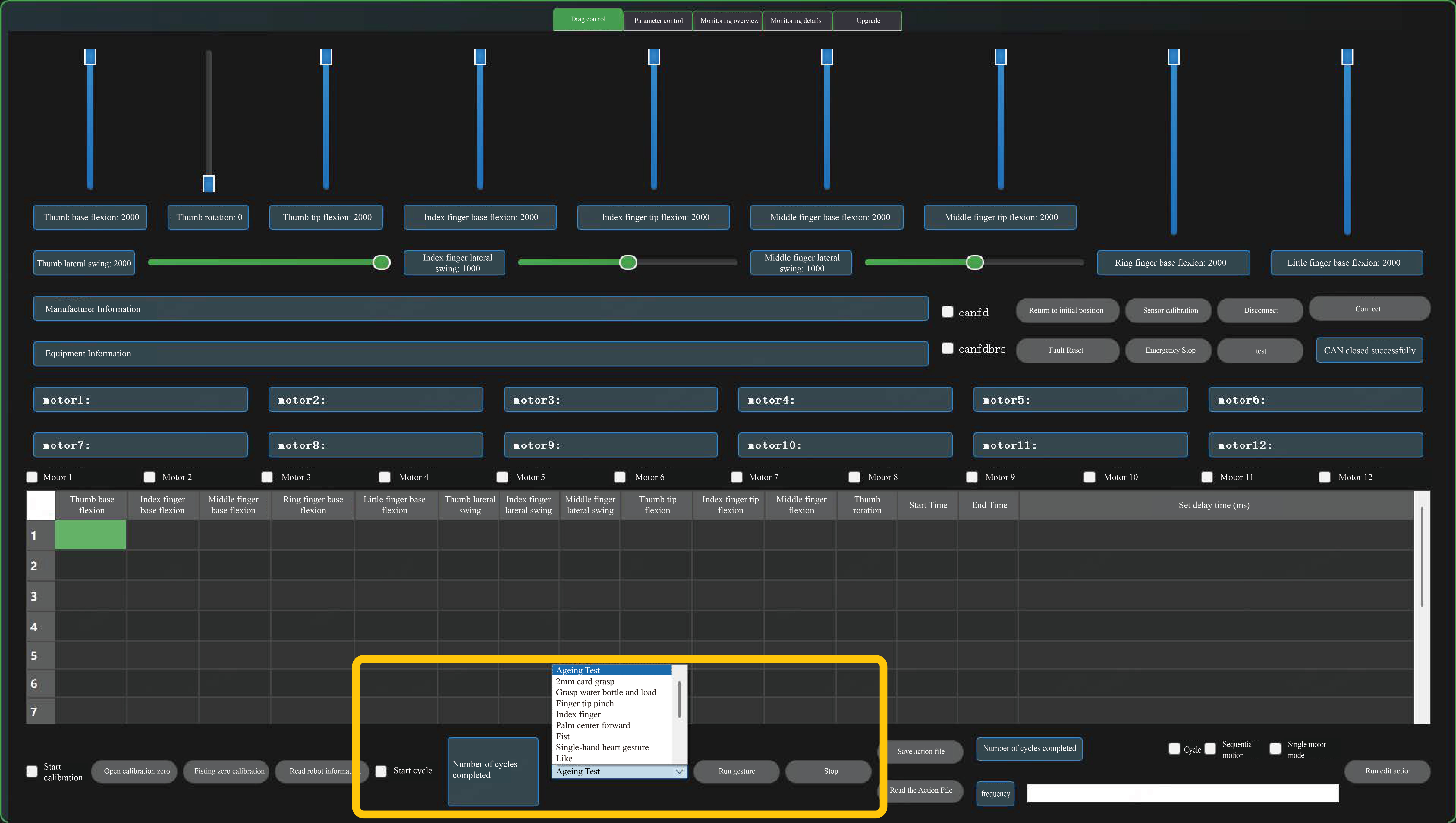
You can click the "Run Gesture" button to execute a preset gesture;
Check "Loop", enter the number and then click "Run Gesture" to cycle through all preset gestures; Click "Stop" to stop the cycle.
5.5 Zero Calibration
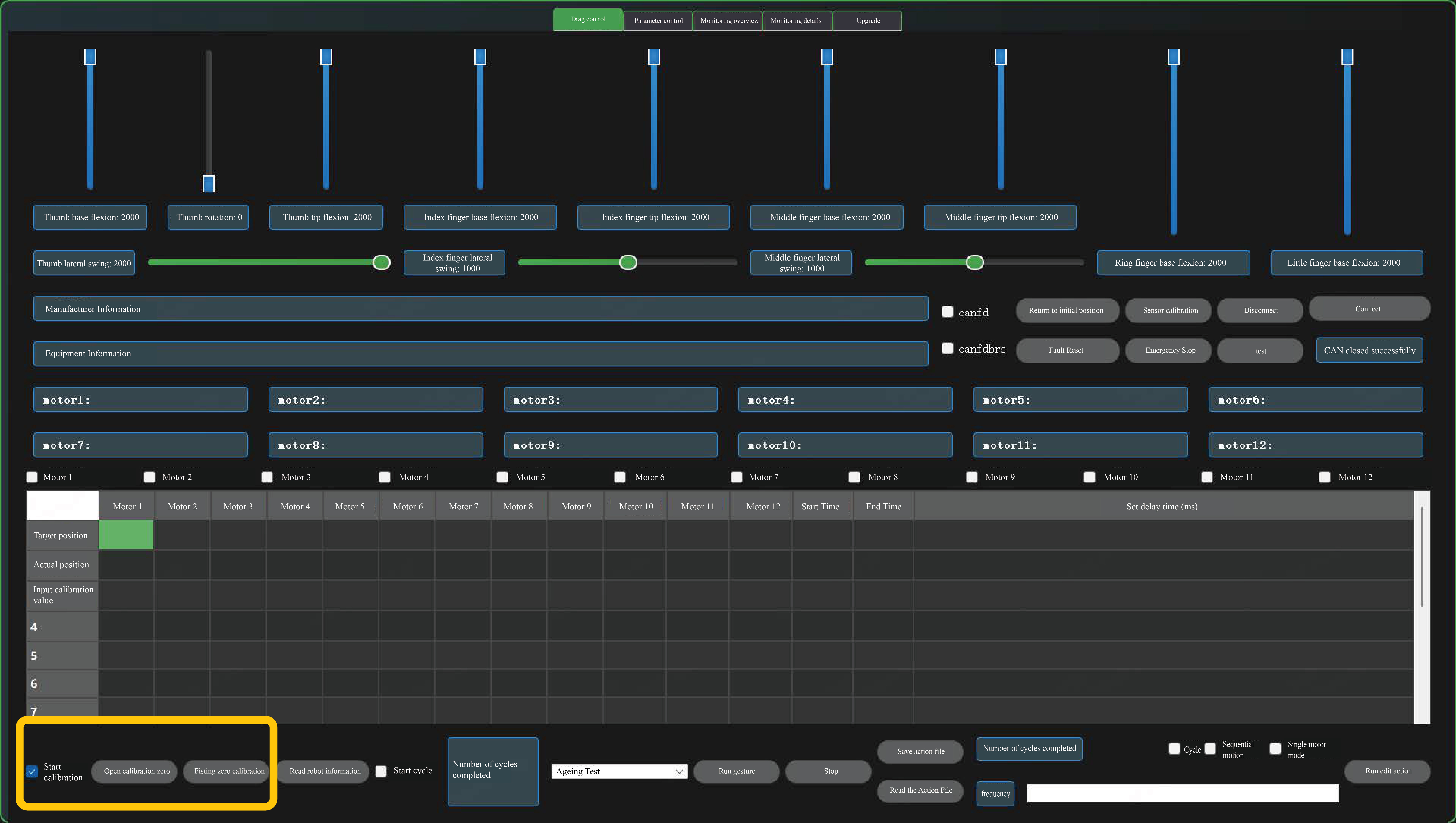
Check "Start Calibration" on the bottom left, right-click to get target/actual calibration positions, enter motor calibration values in the input row and check the corresponding motor checkbox.
Click "Open Zero Calibration" to set the open position zero point.
Click "Fist Zero Calibration" to set the fist position zero.
5.6 Information Reading and Fault Reporting
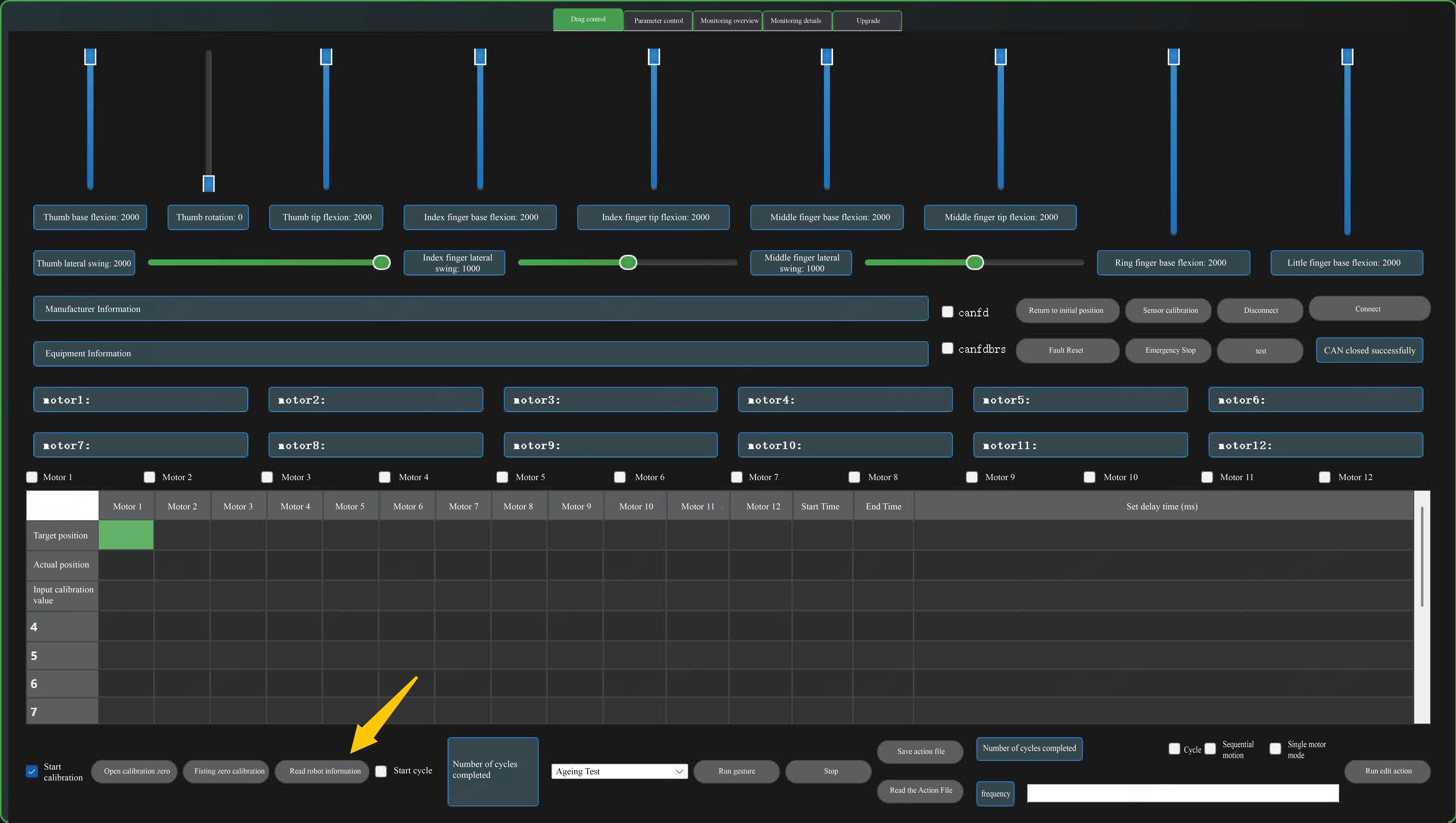
Click "Read Info" to display details in the manufacturer and device information fields.
Motor 1 to Motor 12 display fields show fault codes actively reported by the host.
5.7 Monitoring Overview
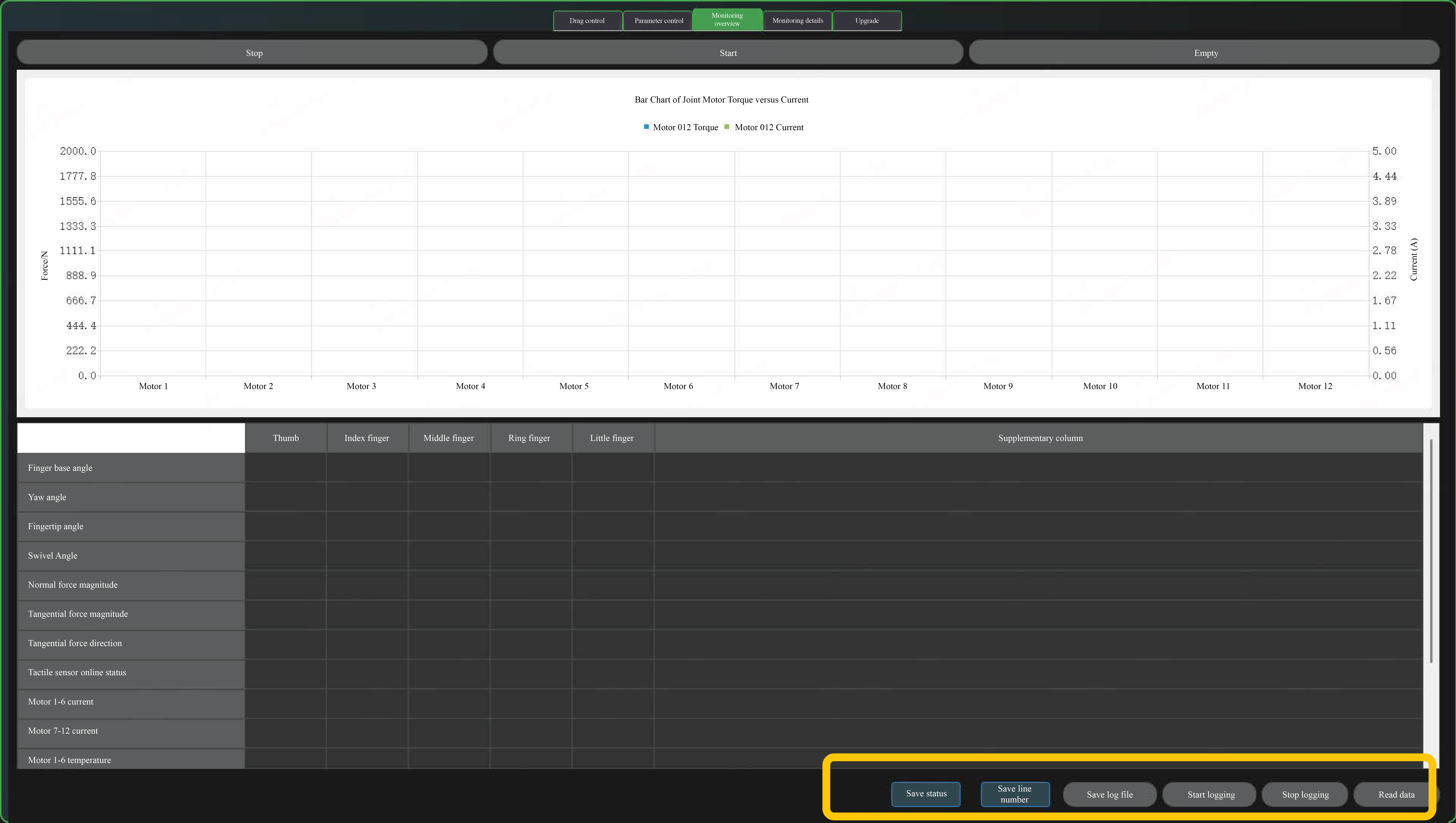
Click the "Start" button to display force and current values.
You can click the "Read Data" button to display corresponding data in the table.
You can click the "Start Logging" button to record temperature, current, error code and torque value; click "Save Log File" to save the recorded data. If not clicked, data will be auto-saved once every 5 minutes to the host program folder.
5.8 Monitoring Details
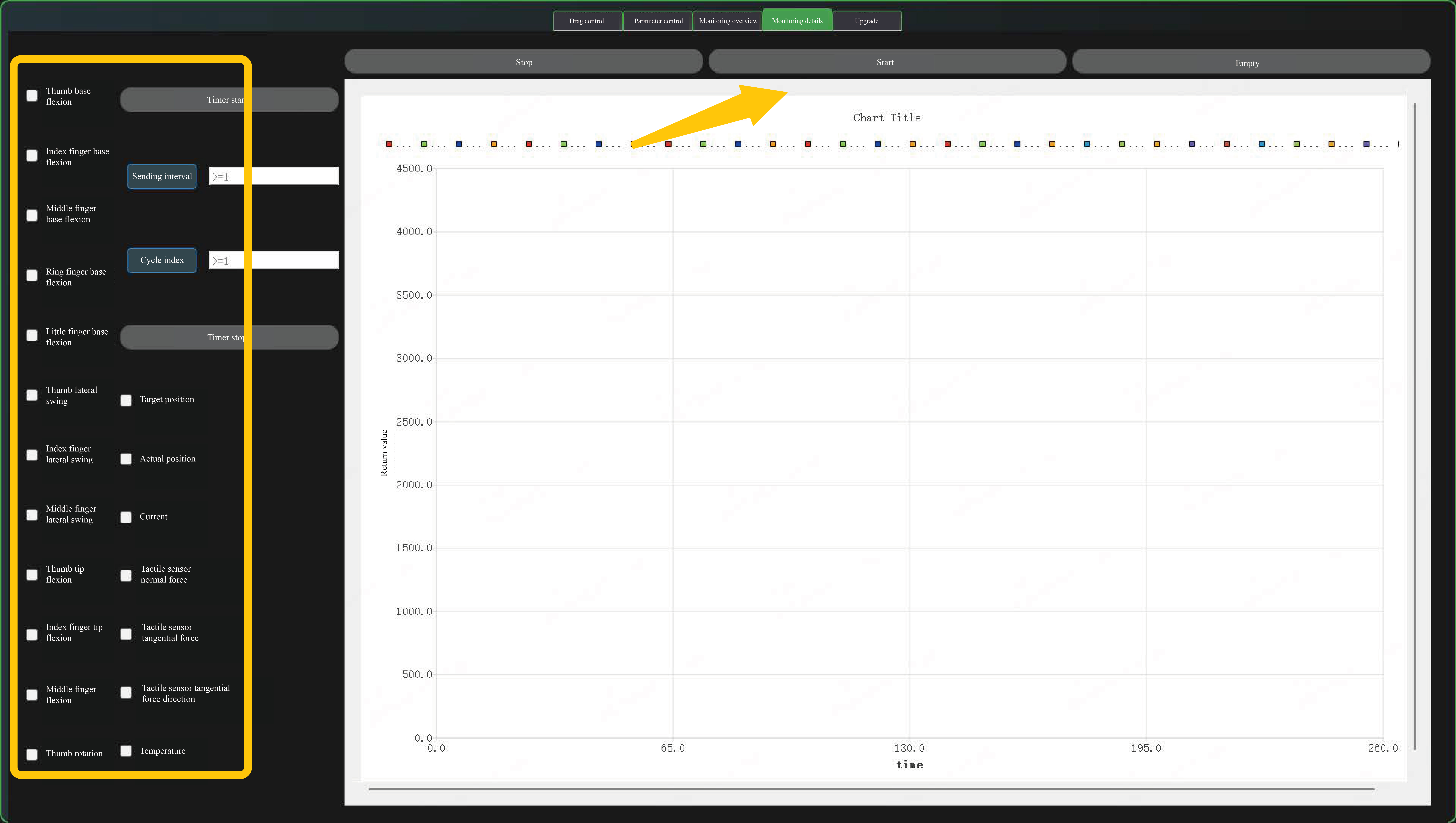
Tick the box before the type of information you want to check, then select the corresponding finger or motor and click "Start" to check the curve.
5.9 Upgrade
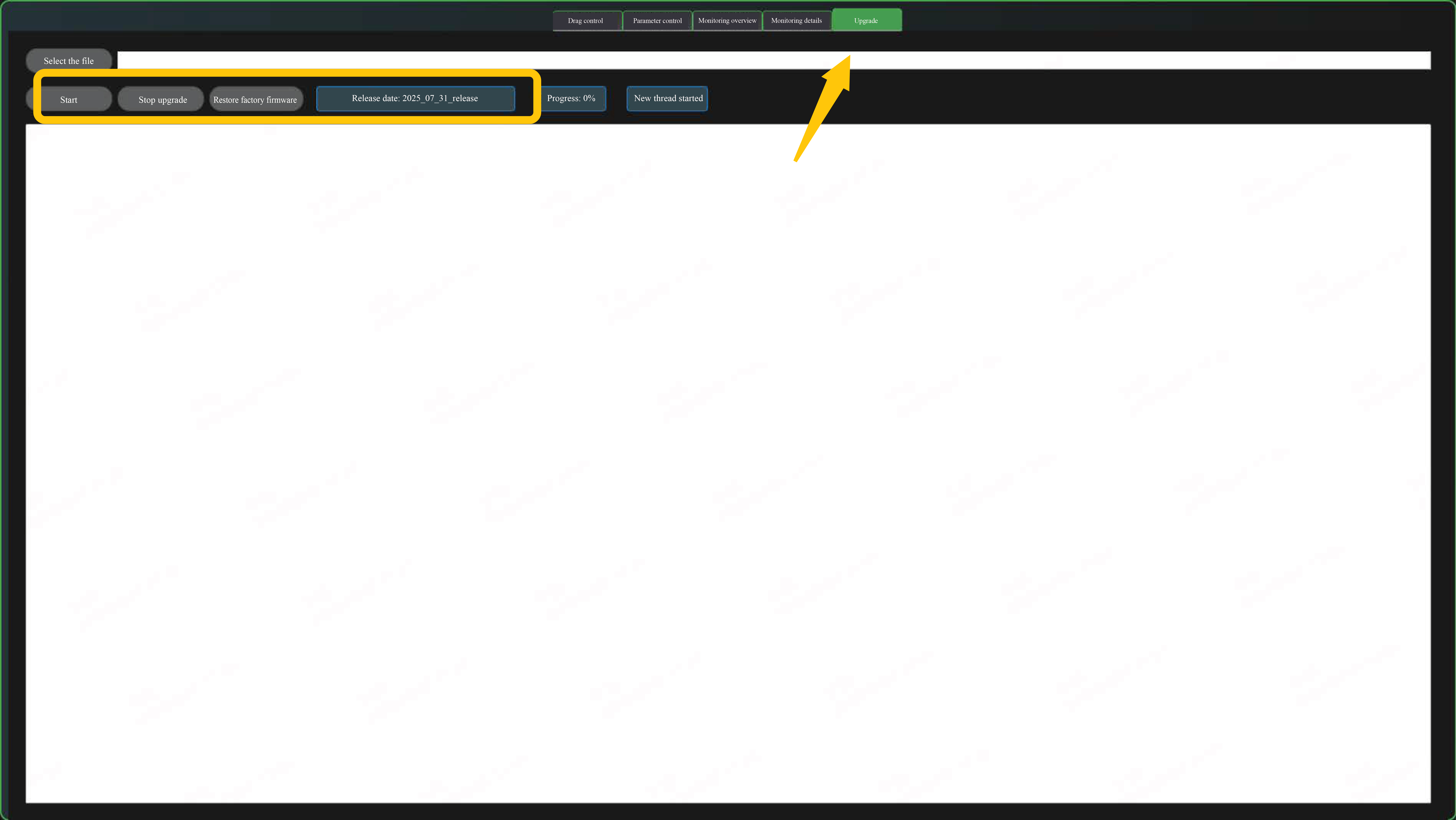
You can click the "Select File" button to choose the bin file for transfer.
If you click the "Start" button, software and hardware information will pop up. Click "Yes" to initiate firmware transfer. Click "No" to cancel upgrade.
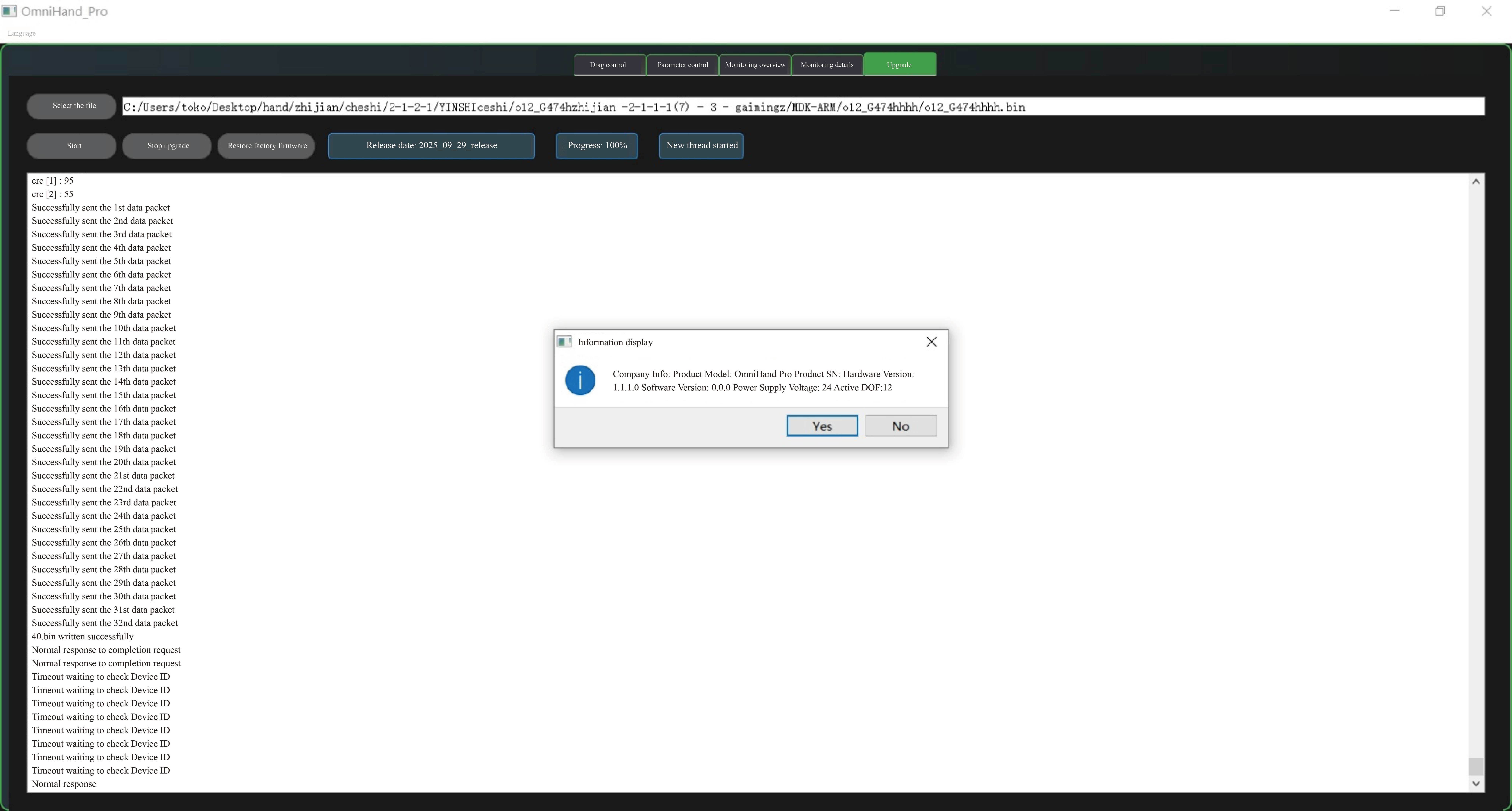
Both "Stop Upgrade" and "Factory Reset" can be clicked in the process of upgrade or in the case of reconnection after power outage.
"Stop Upgrade" allows interrupting the upgrade process to run the previous APP.
"Restore Ex-factory Firmware" is to restore the ex-factory firmware.
