

Important Notices
This chapter describes the important notices that must be observed when installing and using the OmniPicker gripper. The OmniPicker gripper is partly completed machinery. Before first use, read this manual carefully to fully understand the relevant safety warnings and risks. Personnel must carry out a risk assessment before each installation of the OmniPicker gripper, and strictly follow all instructions and guidance in this manual during use.
1.1 Safety Warnings and Precautions
Never place OmniPicker in high-temperature, high-humidity, flammable or explosive environments. Keep it away from fire sources, and never use it in strong electromagnetic fields (e.g., near high-voltage power lines or high-power machinery).
Never apply excessive force to the gripper fingers or pull the gripper forcibly. Do not subject OmniPicker to excessive loads or impacts.
Never use OmniPicker to grasp objects that are excessively heavy, hot, sharp, rough-surfaced, or corrosive.
Never use OmniPicker to operate hazardous machinery. The Company assumes no liability for personal injury or property damage arising from such use.
Minors must never operate OmniPicker unsupervised. Where use is necessary, it must take place under the full supervision and guidance of qualified adult personnel.
Personnel who have not received product safety training, or who are unfamiliar with the operating logic and safety rules of the device, must not independently perform powered operation or debugging.
Never operate OmniPicker under the influence of alcohol or fatigue, or after taking medication that impairs judgment or reaction. Persons with limited mobility or cognitive ability must not operate it independently.
Before operation, make sure all cables, plugs, and sockets are intact. Disconnect the power supply immediately in case of abnormal conditions (e.g., short circuit, overheating).
1.2 Potential Risk Assessment
Mechanical hazards: crushing, abrasion, or similar injuries caused by contact with OmniPicker or with sharp objects it is holding.
Electrical hazards: electric burns or electric shock caused by contact with live parts.
High-temperature hazards: skin burns caused by prolonged contact with hot surfaces of OmniPicker.
Noise hazards: none.
Vibration hazards: none.
Radiation hazards: none.
Material/substance hazards: none.
Ergonomic hazards: pinching injuries caused by contact with gaps between components.
Environmental hazards: none.
1.3 Warranty and After-sales Service
OmniPicker carries a 6-month warranty. During the warranty period, if defects attributable to defective manufacturing or materials occur after the product is put into use, the Company will provide the necessary spare parts for replacement or repair. This warranty becomes void if the defect results from improper handling, failure to follow the information described in the user guide, or unauthorized disassembly of the product. Without prejudice to this warranty, for products beyond the warranty period, the Company reserves the right to charge the customer for replacement or repair. If a defect occurs outside the warranty period, the Company assumes no liability for any resulting damage or loss, including but not limited to loss of production or damage to other production equipment.
Except for the disassembly operations explicitly permitted in this manual, never disassemble OmniPicker; doing so will void the warranty clauses of the Sales Agreement. In the event of any malfunction, please contact after-sales service personnel promptly.
1.4 Disclaimer
The Company is committed to continuously improving product reliability and performance, and therefore reserves the right to upgrade the product without further notice. The Company has made every effort to ensure the accuracy and completeness of this manual. Due to continuous product improvement, version updates, or typesetting and printing, the contents of this manual may differ from the actual product; the actual product and the latest information released by the Company shall prevail. Failures caused by the following circumstances are not covered by the warranty:
Failure to install, wire or connect other control devices as required by the user manual;
Unauthorized disassembly/assembly of the OmniPicker;
Use of OmniPicker beyond the specifications or standards stated in the user manual;
Damage resulting from improper transportation;
Damage caused by accidents, impacts, or collisions;
Damage caused by natural disasters, including but not limited to fire, earthquakes, tsunami, lightning strikes, strong winds and floods.
The gripper does not support hot-plugging of power or signal cables while powered on. Users must follow proper operating procedures; the customer bears the corresponding responsibility for failures caused by improper hot-plugging.
The Company shall not be held liable for any loss, damage, injury or expense caused by customers violating the disclaimers in this section. Customers are kindly requested to carefully read and agree to this disclaimer before purchasing and using the product.
1.5 Maintenance and Care Instructions
To keep OmniPicker running stably over the long term, please observe the following care and storage requirements.
For long-term storage, keep the product in a clean, dry, well-ventilated environment at a suitable temperature, away from strong light, corrosive gases, strong electromagnetic interference, and fire or heat sources.
For long-term storage, disconnect the power and signal cables, and avoid leaving the gripper under sustained force, bending, compression, or in a suspended state for extended periods. Protect the product with its original packaging or with dust-proof, shock-proof packaging.
Without protection, never allow OmniPicker to come into contact with liquids (alcohol, water, beverages, etc.), sand, dust, or corrosives, and keep it out of the rain. In case of accidental contact, cut off the power immediately and check the condition of the connectors, joints, and housing.
Do not rinse the gripper with water, immerse it, or spray it with cleaning fluid. Do not clean it with alcohol, strong acids or alkalis, corrosive cleaners, volatile solvents, or abrasive materials. Use a clean, dry soft cloth to wipe dust off the hard housing surfaces.
Perform regular maintenance and inspection to ensure that components such as the motor and power supply operate normally, and to avoid hazards caused by aging or damage.
If the gripper fails, do not disassemble it or force continued use. Record the failure symptoms, time of occurrence, operating environment, load conditions, and any abnormal indications, and contact after-sales service personnel promptly. Damage caused by unauthorized repair, disassembly, modification, or use of non-original parts may void the warranty; the associated risks are borne by the user.
Introduction
2.1 Product Overview
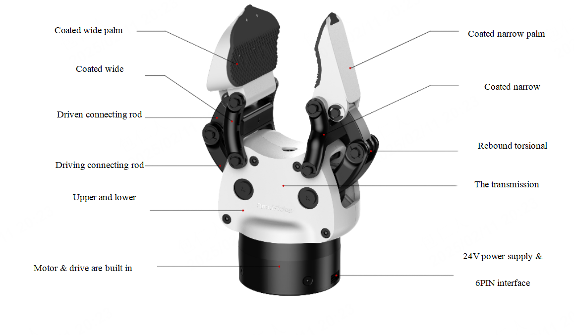
OmniPicker is an adaptive, general-purpose gripper. It combines the advantages of different gripper designs and can grasp objects of various shapes with only one active degree of freedom. The product is very lightweight and easy to use, with a weight of only 430g.
OmniPicker is highly versatile and suitable for a wide range of grasping tasks. It can be integrated with various robot platforms such as humanoid robots, industrial arms and collaborative robots. OmniPicker provides multiple software communication protocol interfaces to help users complete integration quickly. In addition, the gripper features active force control capabilities, enabling tasks such as data collection and light-duty tasks.
2.2 Features
Cost-effective hardware design
Adaptive mode & gripping force adjustable
Supports self-locking gripping force
Feedforward force control
Integrated actuator
2.3 Basic Information
Model | OmniPicker |
|---|---|
CE-EMC certification | Compliant with EN IEC 61000-6-1/6-2/6-3/6-4
|
RoHS certification | RoHS compliant |

2.4 Technical Specifications
Parameter | Typical value |
Weight | 0.43kg |
Max gripping force | 30N |
Payload | 1.5kg |
Max gripper stroke | 120mm |
Min opening/closing time (Typ) | 0.7s |
Positioning repeatability | ±0.05mm |
Communication Protocols | CAN、CAN-FD、RS485、Serial、Modbus RTU |
Operating Voltage | 24V DC |
2.5 Environmental Protection and Disposal Statement
This product falls within the scope of waste electrical and electronic equipment. Please dispose of it in accordance with the requirements of the WEEE (Waste Electrical and Electronic Equipment) Directive. Do not dispose of the product together with ordinary household waste. At the end of its life, deliver it to a qualified local e-waste collection and recycling facility for professional sorting and treatment, so as to recover resources, ensure environmentally sound disposal, and reduce the potential impact on the environment.
This product strictly complies with RoHS environmental regulations; the hazardous-substance content of all components is within the statutory limits.
2.6 Manufacturer Information
Manufacturer | Shanghai AGILINK Innovation Technology Co., Ltd |
Address | Room 1107, 11th Floor, No. 185 Tianping Road, Xuhui District, Shanghai, China |
Contact | +86-21-20960883 |
Operation Guide
3.1 Packing List
OmniPicker *1
CAN-FD communication cable *1
3.2 Instructions
The following materials are prepared with AgiBot X1 Universal Humanoid Package as shown in Chart 1, please prepare the necessary installation tools, as shown in Chart 2.
S/N | Material name | Quantity |
1 | OmniPicker | 1 |
2 | Ultra-short hexagon socket screw M3x6 | 3 |
3 | End cap | 1 |
4 | Adapter flange | 1 |
5 | Hexagon socket head cap screw M4x8 | 4 |
6 | Connecting flange | 1 |
S/N | Tool name | Model/specification |
1 | Hexagon key wrench | H2 |
2 | Hexagon key wrench | H2.5 |
3 | Hexagon key wrench | H3 |
Complete the installation in accordance with the following steps
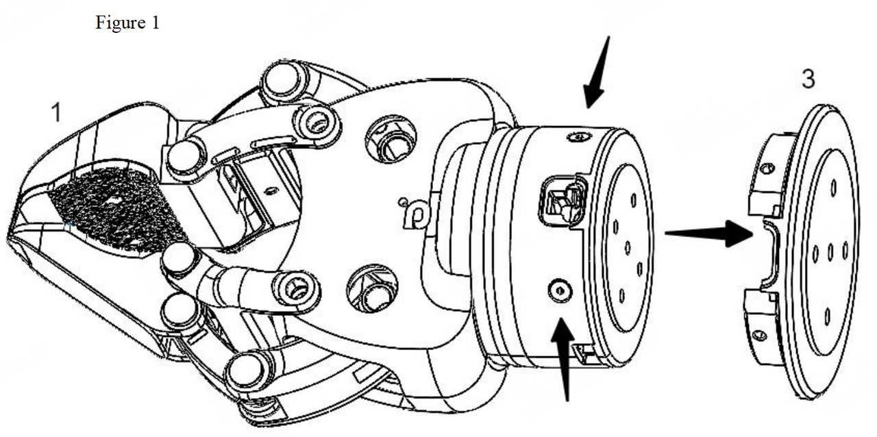
STEP1: As shown in Figure 1, remove the four countersunk head hexagon socket head cap screw M2.5x8 at the bottom of OmniPicker with a H2 hexagon key wrench to get the end cap;
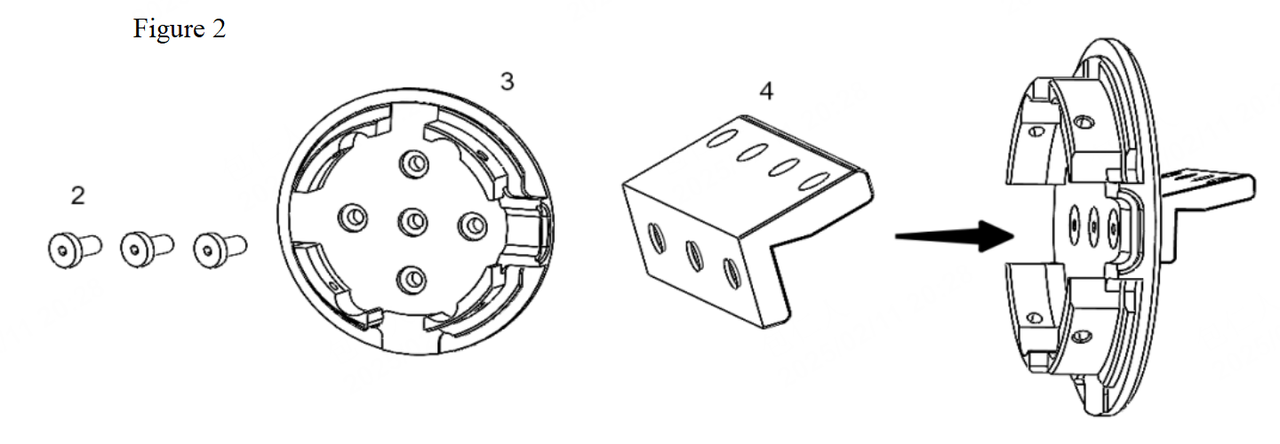
STEP2: As shown in Figure 2, screw three ultra-short hexagon socket head cap screws M3x6 into the end cap with a H2.5 hexagon key wrench and fix on the adapter flange;
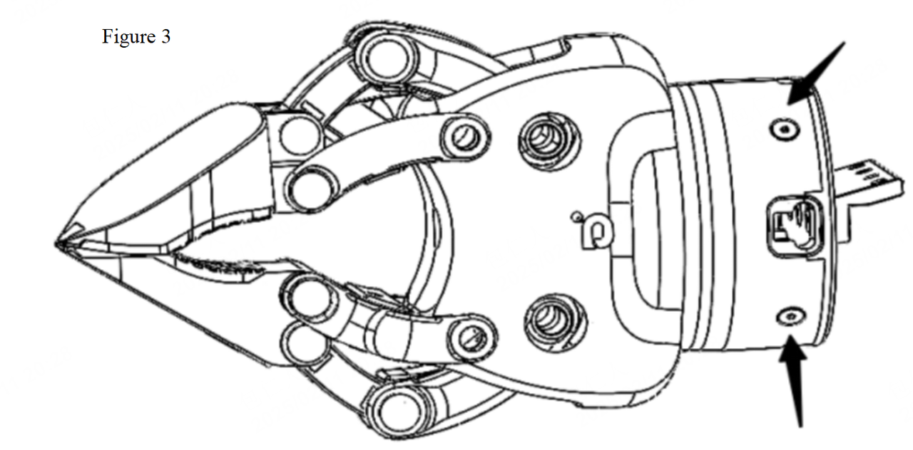
STEP3: As shown in Figure 3, use a H2 hexagon key wrench to replace the four countersunk head hexagon socket head cap screws M2.5x8 removed in Step 1 on the gripper;
STEP4: As shown in Figure 4, use a H3 hexagon key wrench to fix the gripper with four cylindrical hexagon socket head cap screws M4x8 on the connecting flange;
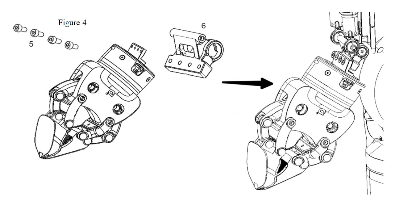
STEP5: The left and right grippers are installed in the same way, and all the wide fingers of the gripper are close to the outside of the body after installation;
STEP6: If the obtained gripper has great resistance when the screws are removed in STEP1, it may be because threadlocker was applied when the screws were fastened. In this case, it is recommended to use a hot air gun to heat the screws before removal.
STEP7: Insert the cable.
NOTE: Pay attention to the installation direction when the end cap and the adapter flange are installed.
3.3 Use of other robots
If users connects OmniPicker to other robotic arms, it is allowed to refer to the following installation interface drawings to design the adapter.
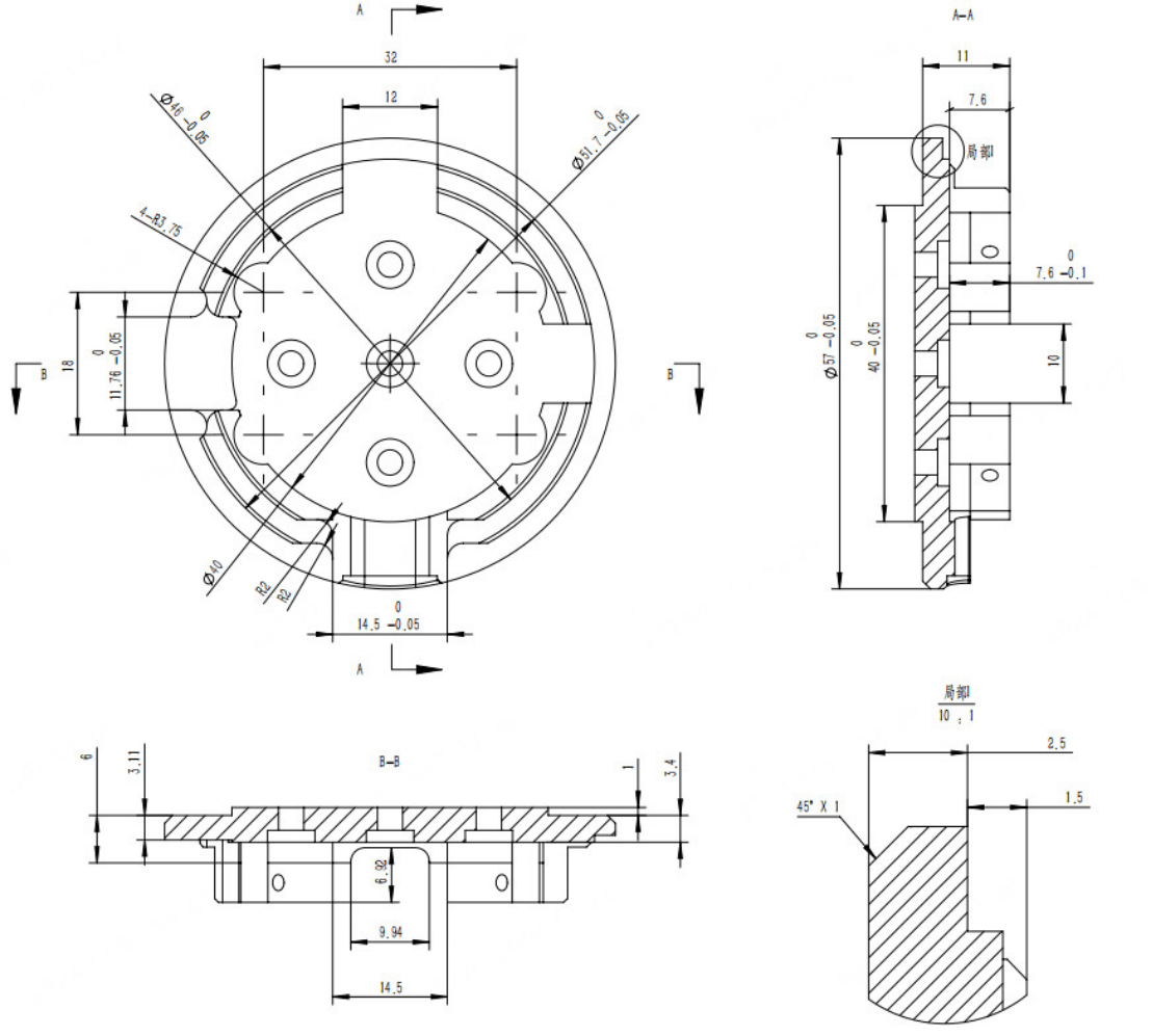
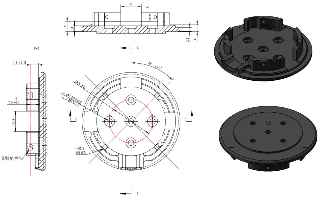
3.4 Troubleshooting
Common Issue | Solution |
|---|---|
Wear of the soft pads on the gripper fingers | Replace the fingers (or soft pads) |
Screws loosen after removal and re-tightening | Do not reuse screws once removed; replace them with new ones |
The indicator LED reports an error after power-on | Recalibrate the gripper |
SDK troubleshooting | For common issues when driving the Picker via the SDK, see:https://github.com/AgibotTech/agillink_omnihand_sdk/blob/main/doc/zh_cn/TROUBLESHOOTING.md |
Host software troubleshooting | For host-software issues such as firmware upgrade failures, refer to Section 6.2 Host Software |
3.5 Other Common Operations
Debugging, operation, start/stop, and other actions can be performed with the host software. For instructions, see Section 6.2 Host Software.
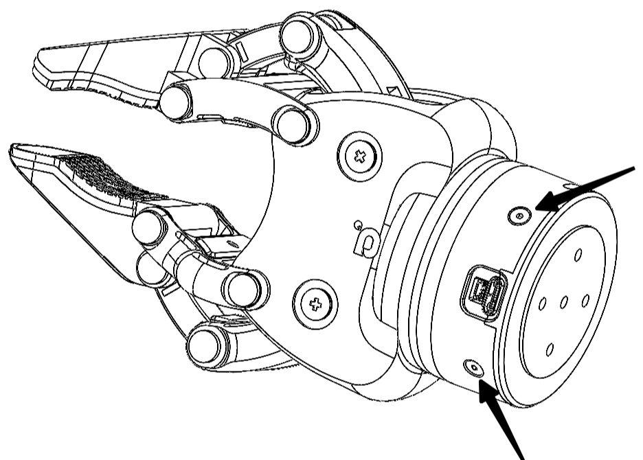
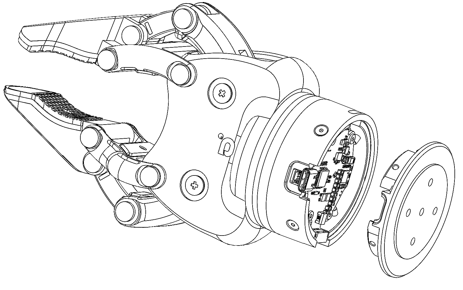
Board side: only removal of the rear cover is recommended; removing the board itself is not. Before removing the rear cover, loosen the four M2.5 screws as shown below. After taking out the four screws, gently pry the rear cover open with a thin steel sheet to expose the board surface for DIP-switch operation.
 |  |
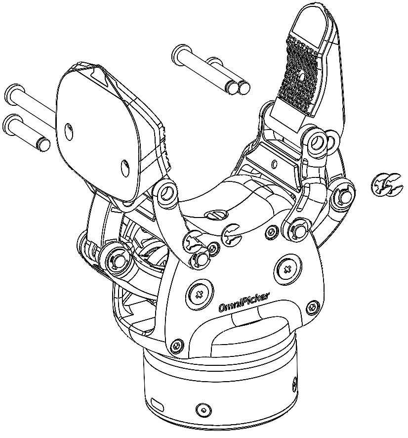
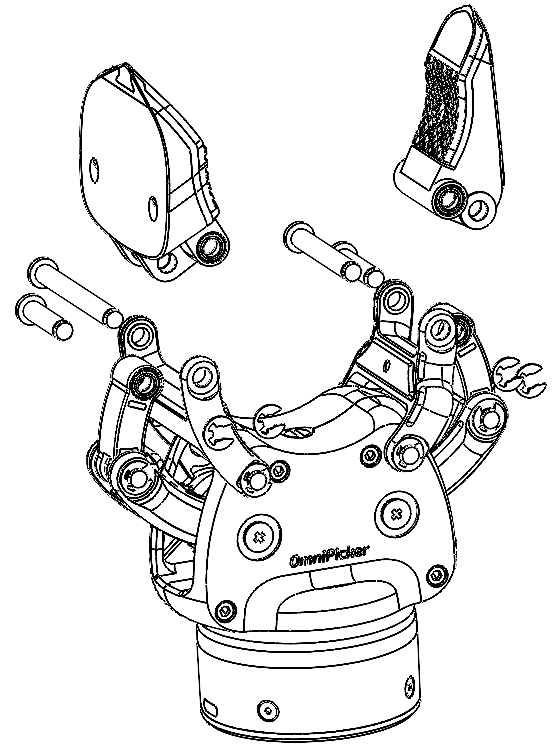
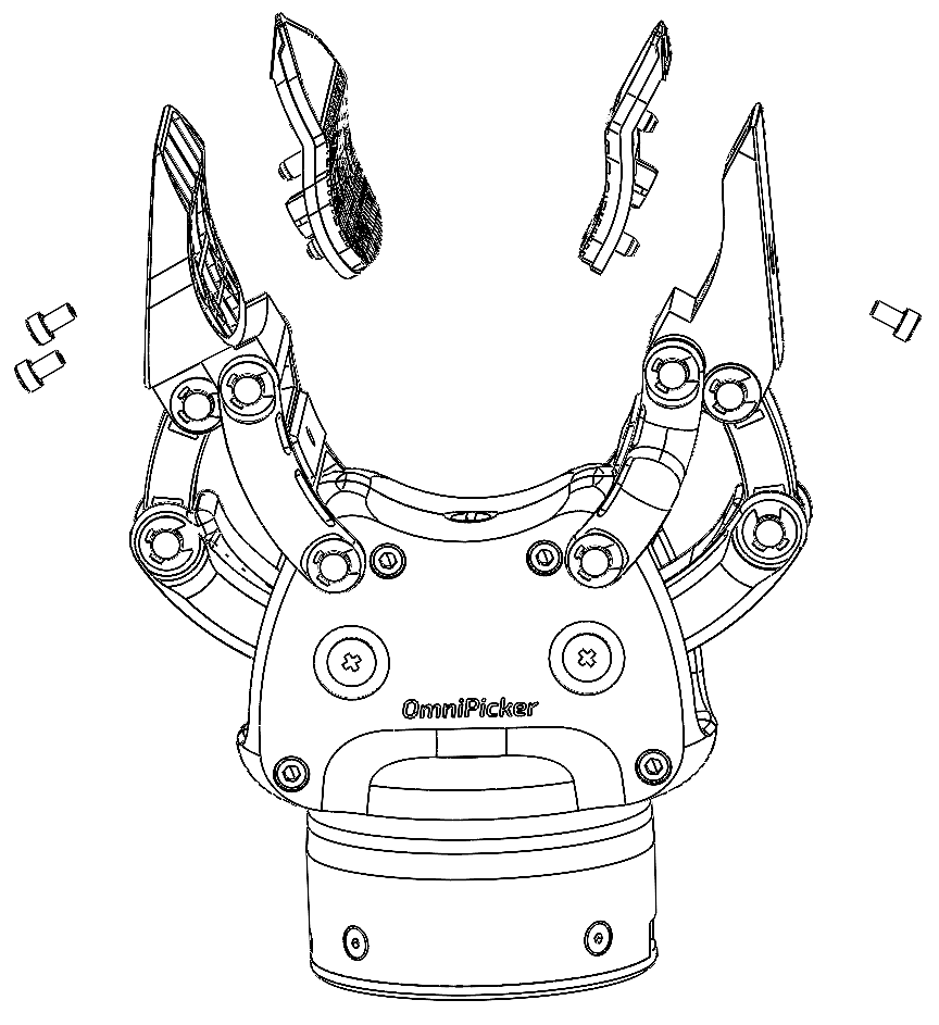
Finger side: replacing the fingers or soft pads: (1) Remove the four circlips connecting the wide and narrow fingers and take out the pins; the fingers can then be replaced.
 |  | 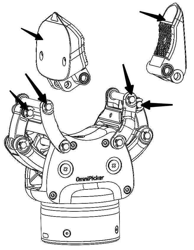 |
(2) If a soft pad is defective and the pad base can be detached from the finger, the pad base can be removed separately: first remove the M2.5 screws on the finger — two on the wide finger and one on the narrow finger. Once the screws are removed, detach the pad base and fit a new soft pad.
Product Dimensions
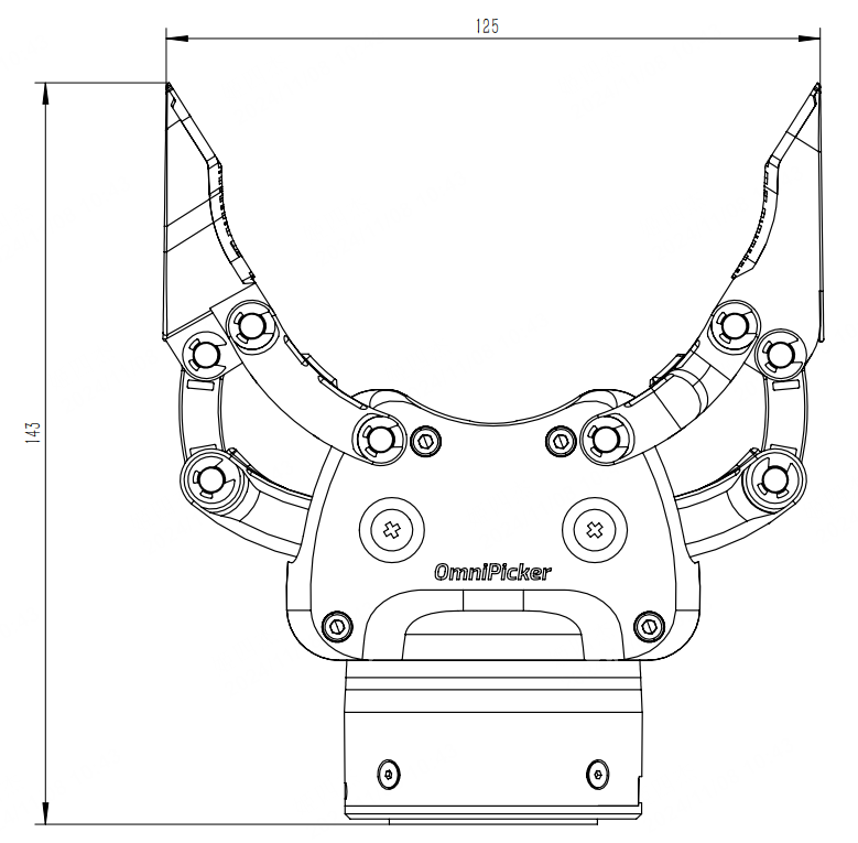
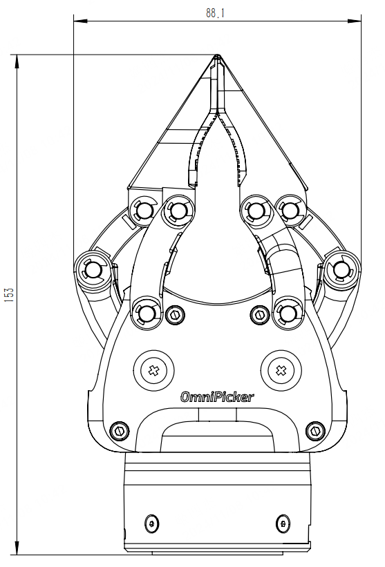
4.1 Dimensional Drawing
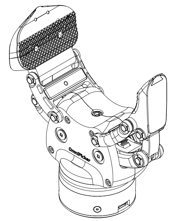
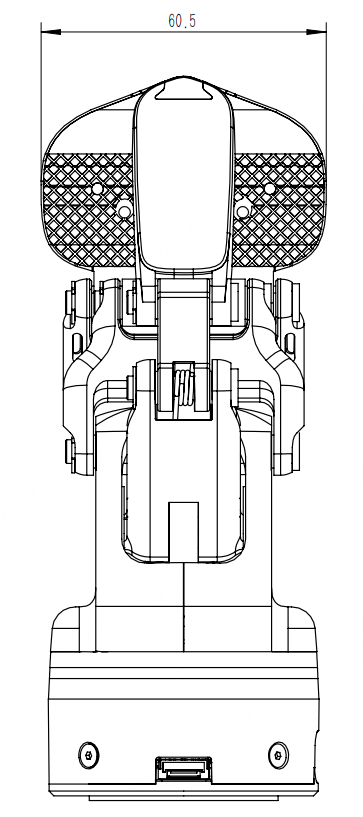
The following shows the external dimensions of OmniPicker in the opening and closing states.
|
|
|
|
Electrical Interface
5.1 6 PIN Interface
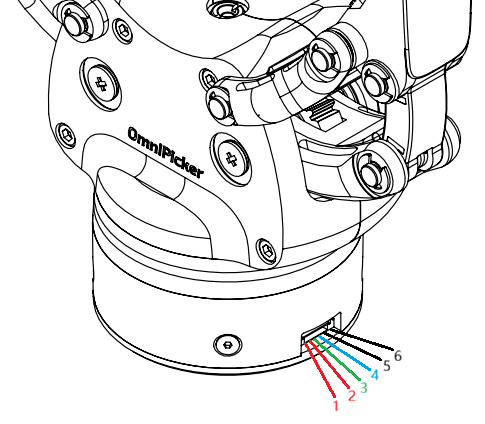
The external electrical interface of OmniPicker uses 6PIN socket with lock at a distance of 1.25mm.
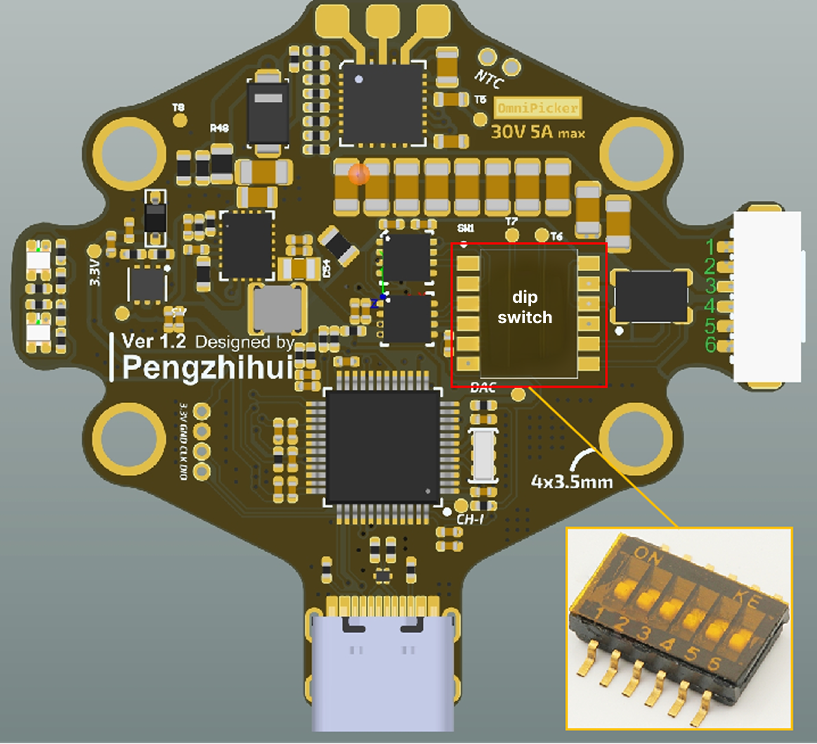
The red box in the control panel is a dip switch, and its interface pins are defined as shown in the following table:
S/N | Definition of PIN | Function Description |
1 | VIN | Pins 1 and 2 are used as power input, and the voltage does not exceed 24V DC. |
2 | VIN | |
3 | L | UART2_RX or RS485_B or FDCAN2_L. |
4 | H | UART2_TX or RS485_A or FDCAN2_H. |
5 | GND | Pins 5 and 6 are used as GND for power supply. |
6 | GND |
5.2 Communication Modes
When the end cap of the machine is opened, the state of the gripper PCBA can be distinguished according to the markings shown in the red box in the figure below. Select different operating modes based on this information.
The red box in the control panel is dip switch, operate as below.
The default is CAN/CAN-FD, pins 3 and 4 are in the ON state, and the other pins are in the OFF state.
If it is necessary to switch to RS485, pull pins 1 and 2 to ON, and recover other pins to OFF.
If it is necessary to switch to UART, pull pins 5 and 6 to ON, and recover other pins to OFF.
|
|
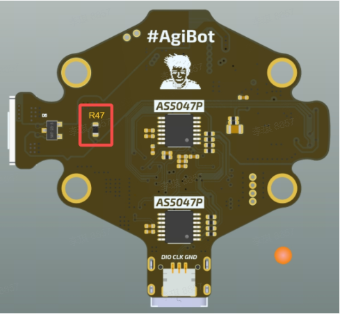
A 120 Ω termination resistor is soldered on the back side of the PCBA. Whether it should be kept depends on the application scenario. The resistor is located at R47 inside the red box in the figure below.
When using CAN / CAN-FD / RS485 communication, this resistor must be kept. It is soldered by default at the factory.
When using UART‑TTL communication, this resistor must be manually removed.
Communication Interface and Protocols
OmniPicker is equipped with multiple communication interfaces to adapt to different working environments.
Configuration steps are as follows:
Select the corresponding communication interface in accordance with the instructions in 5. interconnection of electrical interface. The default is CAN/CAN-FD
Configure gripper parameters through USB connection to the Host
Connect the gripper into the corresponding hardware systems
6.1 LED indicator lights
LED | Defination |
|---|---|
Green: blinking | Disable |
Green: steady on | Enabled (enabled automatically by default at power-on) |
Red: steady on | Error |
Blue: steady on | Motor Calibration in progress (factory-calibrated by default) |
Multi-color: blinking | Firmware upgrading |
6.2 Host Software
The host can modify parameters via the commands. It is recommended to fully understand the configuration parameters before first use.
How to use
Prepare a Windows computer and download the host software REF-CLI v1.0.3.exe .
First, make sure that there are no obstacles between the stroke of the gripper, then power on the gripper. The gripper will automatically close to zero position. In case of failure, it is required to stop and check whether the gripper moves smoothly.
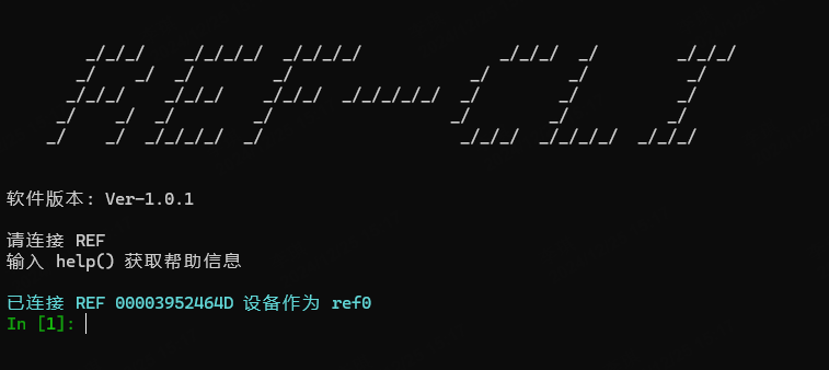
Connect the gripper to the computer with a USB-C cable, and open the host software. Once the host identifies the device successfully, the following display will appear:
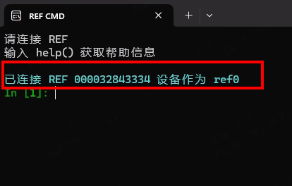
At this point, the device with SN 000032843334 has the index name ref0 in the host software.
Note: If multiple grippers are connected, their index names in the host will be arranged in sequence: the first is ref0, the second is ref1, and so on. Be sure to modify commands according to the corresponding device number. After closing and restarting the host software, indexing will start again from ref0.
In the host software, type ref0 directly and press Enter to show the basic information of the current gripper. As shown in the figure, the current gripper’s firmware version is 1.3.4, and the CAN bus ID is 8.
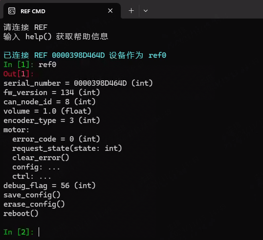
Modify CAN-ID
ref0.can_node_id represents the node ID of CAN bus. It is allowed to view its value directly, or use = to assign values. Execute the following command.
ref0.can_node_id=8 // CAN ID sets to 8
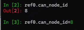
All parameter changes need to be saved by calling save_config() method, and this operation needs to be carried out in the Disabled state.
ref0.motor.request_state(0)    // First disable the gripper. 0 - disabled, 1- enabled
ref0.save_config()             // Save all the parameters
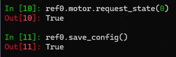
Note: All parameter changes take effect only after saving and power-cycling the device.
Control the Gripper
Power on the gripper again. (Default self-enabled upon power-on)
Wait for the gripper to close automatically
Connect the host and call
set_pos(x)to set its position, wherexis the opening and closing percentage, with the range of0.0-1.0,0means closed and1means fully open.
ref0.motor.ctrl.set_pos(0.5) // Gripper open 50%
6.3 CAN/CAN-FD Communication Protocols
When the gripper communicates with CAN-FD, the baud rate is 1M in arbitration domain (80% sampling point) + 5M in data domain (75% sampling point), and it is compatible with CAN protocol with a baud rate of 1M (80% sampling point).
Note: The firmware version of CAN protocol is not less than 3.3.0.
Downstream Protocol
CAN ID | DLC | D0 | D1 | D2 | D3 | D4 | D5 | D6 | D7 |
|---|---|---|---|---|---|---|---|---|---|
can_node_id | 8 | Reserved | Pos Cmd | Vel Cmd | Force Cmd | Acc Cmd | Dec Cmd | Reserved | Reserved |
ID: downstream control ID of the gripper, corresponding toref0.can_node_idReserved: reserve, write0Pos Cmd: target position, range0 - FF,0is close,FFis fully openVel Cmd: target velocity, range0 - FF,FFis max velocityForce Cmd: target torque,range0 - FF,FFis max torqueAcc Cmd: target acceleration,range0 - FF,FFis max accelerationDec Cmd: target deceleration,range0 - FF,FFis max deceleration
E.g. If the gripper is controlled to run to 50% of the stroke, all other parameters can be given the maximum value:
Send message 00 7F FF FF FF FF 00 00
Upstream Protocol
After power-on and successful enabling, every time the gripper receives a control command, the state data of the a frame will be reported immediately. The state frame is defined as follows.
CAN ID | DLC | D0 | D1 | D2 | D3 | D4 | D5 | D6 | D7 |
|---|---|---|---|---|---|---|---|---|---|
can_node_id | 8 | Fault Code | State | Pos | Vel | Force | Reserved | Reserved | Reserved |
ID:upsteam message ID of the gripper, corresponding toref0.can_node_idFault Code: error code, definitions are as following:
Code | Definition |
|---|---|
00 | No fault |
01 | Over heated alarm |
02 | Speed limit exceeded alarm |
03 | Initialization fault alarm |
04 | Limit-exceeding alarm |
State: Current state, definitions are as following:
Code | Definition |
|---|---|
00 | Gripper reached target position |
01 | Gripper moving |
02 | Gripper stalled |
03 | Object dropped |
Pos: current position, range asPos CmdVel: current velocity, range asVel CmdForce:current torque, range asForce CmdReserved:reserve. Bytes D5–D7 will directly copy the data from the sent packet. They can be used for your own checksum/verification, or simply ignored.
6.4 Serial TTL/485 Protocols
Note: The serial bus also supports serial chaining, and the node ID reuses
can_node_id. The firmware version must be 3.3.2 or higher.
When the gripper communicates with serial port TTL or 485, the baud rate needs to be changed to 115200@8N1 (8bit data bit, 0 check bit, 1 stop bit).
In version 3.3.5 and later, the baud rate is given by the uart_baudrate parameter in the host software. The data length is 8 bits, there is no parity bit, and the number of stop bits is given by the uart_stopbits parameter in the host software.
TTL/485 Switch
Connect Omnipicker to the host via a USB-C cable, open the host , input ref0 and enter, to check the value of rs485_mode .
If using TTL, please set the value of
rs485_modeto0and save. Note: remove the resistor on the back of the PCB.
ref0.rs485_mode = 0  // turn off 485 mode,enable TTL

ref0.motor.request_state(0)  // Disable
ref0.save_config()           // Save configuration
If using RS495 , please set the value of
rs485_modeto1and save.
ref0.rs485_mode = 1  // turn on 485 mode,turn off TTL

ref0.motor.request_state(0)  // Disable
ref0.save_config()           // Save configuration
Take effect after saving and restarting.
TTL/485 Configuration
Firmware version 3.3.5 and above supports configuring TTL/RS‑485 communication parameters as well as the communication protocol.
Baud rate
ref0.uart_baudrate = 460800  // baud rate 460800

ref0.motor.request_state(0)  // Disable
ref0.save_config()           // Save configuration
Take effect after saving and restarting.
Stopbits
Code | Definition |
0 | 1 stop bit |
1 | 1.5 stop bit |
2 | 2 stop bit |
ref0.uart_stopbits = 0       // Set as 1 stop bit(can be replaced with the required number)

ref0.motor.request_state(0)  // Disable
ref0.save_config()           // Save configuration
Take effect after saving and restarting.
Communication protocol configuration
The communication protocol is determined by the modbus_mode parameter: if it is False, a custom protocol is used; if it is True, Modbus RTU is used.
ref0.modbus_mode = True      // Set to Modbus RTU

ref0.motor.request_state(0)  // Disable
ref0.save_config()           // Save configuration
Take effect after saving and restarting.
Custom Protocol
Firmware versions earlier than 3.3.5 use the custom protocol.
For versions 3.3.5 and later, the custom protocol is used when the host parameter modbus_mode is set to false.
1. Downstream Protocol
D0 | D1 | D2 | D3 | D4 | D5 | D6 | D7 | D8 | D9 | D10 | D11 |
|---|---|---|---|---|---|---|---|---|---|---|---|
Frame Head | ID | Reserved | Pos Cmd | Force Cmd | Vel Cmd | Acc Cmd | Dec Cmd | Reserved | Reserved | CheckSum | |
Frame Head:frame head,0x4141,2 bytesID: ascan_node_idD3 - D10: as D0-D7, CAN bus downstream protocolCheckSum: The data and checksum for D2–D10 are calculated as shown in the Python code below.
def checksum(buf) -> int:
    ret = 0
    for i in buf:
        ret += i
    return (~ret) & 0xff
E.g. If the gripper is controlled to run to 50% of the stroke, if ID is set to 1, all other parameters can be given the maximum value:
Send message 41 41 01 00 7F FF FF FF FF 00 00 83
2. Upstream Protocol
After power-on and successful enabling, every time the gripper receives a control command, the state data of the a frame will be reported immediately. The state frame is defined as follows.
D0 | D1 | D2 | D3 | D4 | D5 | D6 | D7 | D8 | D9 | D10 | D11 |
|---|---|---|---|---|---|---|---|---|---|---|---|
Frame Head | ID | Fault Code | State | Pos | Vel | Force | Reserved | Reserved | Reserved | CheckSum | |
Frame Head:frame head,0x4141,2 bytesID: ascan_node_idD3 - D10:as D0-D7, CAN bus downstream protocolCheckSum:the calculation method is same as downstream protocol, range is D2-D10
Modbus RTU
For versions 3.3.5 and later, the Modbus RTU protocol is used when the host parameter modbus_mode is set to True.
The gripper’s Modbus slave address is same as can_node_id.
You can control the gripper and obtain its current status feedback by reading and writing Modbus registers.
The Modbus register map is as follows:
Register Address (decimal) | Definition | Details |
0 | Firmware verison | |
10 | Target position | Only the low byte of the register is used. Value range:
|
11 | Target Velocity | Only the low byte of the register is used. Value range:
|
12 | Target Torque | Only the low byte of the register is used. Value range:
|
13 | Target Acceleration | Only the low byte of the register is used. Value range:
|
14 | Target Deceleration | Only the low byte of the register is used. Value range:
|
15 | Motion Trigger flag | Writing a non-zero value triggers the motor to move according to the target position and other parameters in registers 10-14. The flag is automatically cleared when the motor starts executing the motion. |
20 | Current error code | Refer to error code in CAN-FD protocol |
21 | Current status | Refer to status code in CAN-FD protocol |
22 | Current position | Refer to Target position |
23 | Current velocity | Refer to Target velocity |
24 | Current Torque | Refer to Target torque |
1. Motion Control
The user can control the gripper by writing control parameters to registers 10–15 using the Modbus RTU 0x10 (Write Multiple Registers) command.
For example, to move the gripper to 50% of its stroke, assuming the slave address is 1 and all other parameters are set to their maximum values,
send message: 01 10 00 0A 00 06 0C 00 7F 00 FF 00 FF 00 FF 00 FF 00 01 B9 BA
Register 10 (target position):
00 7F→ 0x7F (≈ 50% stroke)Registers 11–14 (speed, torque, etc.):
00 FF 00 FF 00 FF 00 FF→ all set to 0xFF (maximum)Register 15 (motion trigger flag):
00 01→ non‑zero, triggers gripper motion
2. Read Status
The user can read the gripper status by sending a Modbus RTU 0x03 (Read Holding Registers) command to read registers 20–24.
Assuming the slave address is 1, the request frame is:
01 03 00 14 00 05 C5 CD
Function code:
03(Read Holding Registers)Starting register address:
00 14→ 0x0014 = decimal 20Number of registers:
00 05→ read 5 registers (20–24)
6.5 Firmware Upgrade
How to upgrade
1. Power on the gripper and connect it to PC, and turn on the host to ensure that the equipment is successfully connected and initialized.
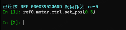
Control the gripper to 50% of the stroke to prepare for calibration. After the command is executed, observe the gripper and confirm that it has been opened to 50%.
Note: This step is very important. Please follow the instructions strictly
Input the upgrade command in the host and wait for the progress to end, where
path_to_firmware_fileis the absolute path of the firmware in the system. Here, version 3.3.0 is taken as an example.
ota(ref0, r"path_to_firmware_file")
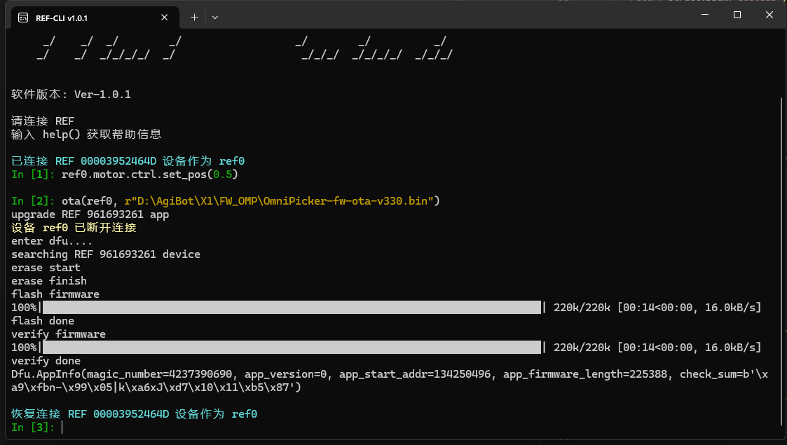
Note: Please be careful not to operate or move the gripper during upgrade, so as not to cause abnormal USB communication.
After the upgrade is completed, the prompt "Restore Link REF XXX" will reappear in the terminal. Check the LED indicator, wait for the green light to start blinking, and then, enter the calibration command.
Note: If, after the upgrade is completed, the gripper closes automatically, skip this step and go directly to step 5.
ref0.motor.request_state(2)

At this point, the LED changes from green blinking to blue steady-on, and the gripper will start to move slowly. Do not operate the gripper during this time and wait for the calibration to complete. When the calibration is successful, the gripper will make a sound, and the LED changes back from blue steady - on to green blinking.
Note: Before performing the calibration, if the gripper fails to open or can no longer be controlled, manually open the gripper according to the following steps.
a. Unplug the power supply and all connection cables.
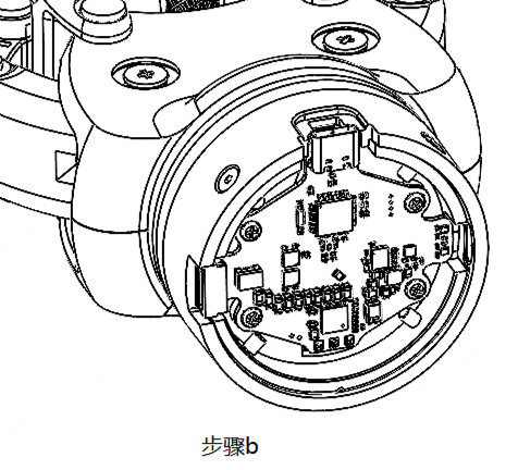
b. Manually remove the rear cover as shown in the figure below.
c. Manually remove the 4 cross-head screws on the control board as shown in the figure below.
d. Lift the control board to expose the magnet. Note that the 3 welded wires of the control board should not be disconnected during the lifting process, as shown in the figure below.
e. Manually rotate the magnet bracket counter-clockwise until the OmniPicker opens about 50% of its stroke, as shown in the figure below.
f. Re-install the control board and tighten the 4 cross-head screws.
g. Put on the rear cover and tighten the screws.
|
|
|
|
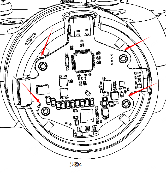
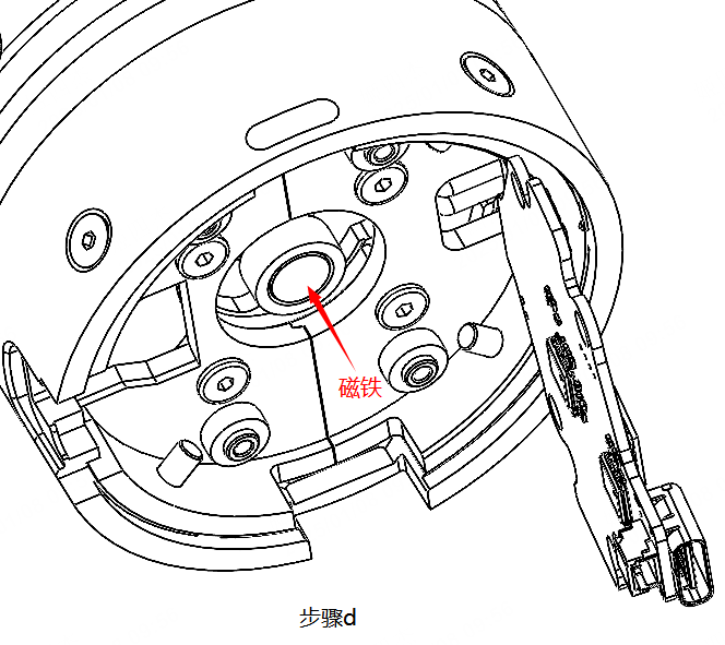
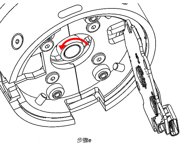
The gripper is powered on again, automatically turns on and closes, and the upgrade is complete.
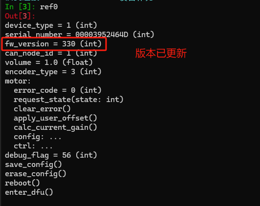
6. If the upgrade fails, use the flash_app command to rewrite the file.
flash_app(r"PATH") // PATH is the absolute path of the firmware in the system

NOTE: the version of REF-CLI has to be 1.0.3 or above
Firmware version
Version | Release Date | Firmware | Contents |
|---|---|---|---|
3.3.0 | 2024.12.26 | https://cn.agilink-ai.com/uploads/upload/files/20260723/97f3875502f1d3787a57938ac77b0763.zip |
|
3.3.3 | 2024.1.10 | https://cn.agilink-ai.com/uploads/upload/files/20260723/f1ff4eb7e7dbe0b786513f573aba21ad.zip |
|
3.3.5 | 2025.12.4 | https://cn.agilink-ai.com/uploads/upload/files/20260723/51b19f395bdf717cbbbf7b916347d8b0.zip |
|
Others
This manual is based on OmniPicker hardware Ver1.2, Firmware Ver3.3.5, and Host Ver 1.0.3 .
URDF
Please use ROS2 Humble to load the URDF file of the gripper.
Download ⬇️
https://cn.agilink-ai.com/uploads/upload/files/20260723/a0ecaeb66b772735e77eb97fff7720a5.zip
